
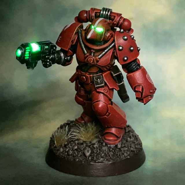

This is my tutorial for placing LEDs inside plasma weapons. The photos show this technique applied to a Assault Intercessor Marine with plasma pistol, but it can equally be applied to regular plasma guns, plasma incinerators, or indeed any other model that you feel would benefit from glowing power cells. This is the updated June 2023 version of this tutorial. If you would like to read the original version from August 2018, it is archived here. If you do not wish to include LED eyes in your miniature and only want the plasma glow, you may want to try my Simple LED Plasma Weapon tutorial instead.
I strongly recommend reading through the entire tutorial before starting work, just to make sure you have the necessary skills and tools required and that you’re not going to run into an unexpected barrier halfway through. If you need to know where to buy tools and consumables for this type of project, I have recommendations here.
I have a separate tutorial about designing LED circuits, basic LED soldering, resin casting and LED eye lenses. This tutorial assumes you’ve either read these, or are familiar with the techniques discussed, especially the eye lens tutorial, which is a starting point this tutorial builds from.
1. Prepare Miniature and Base
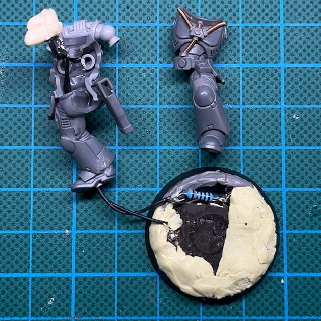
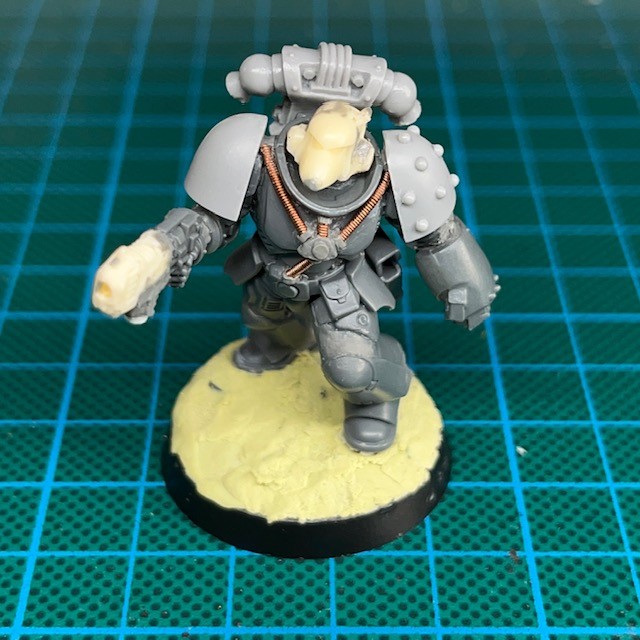
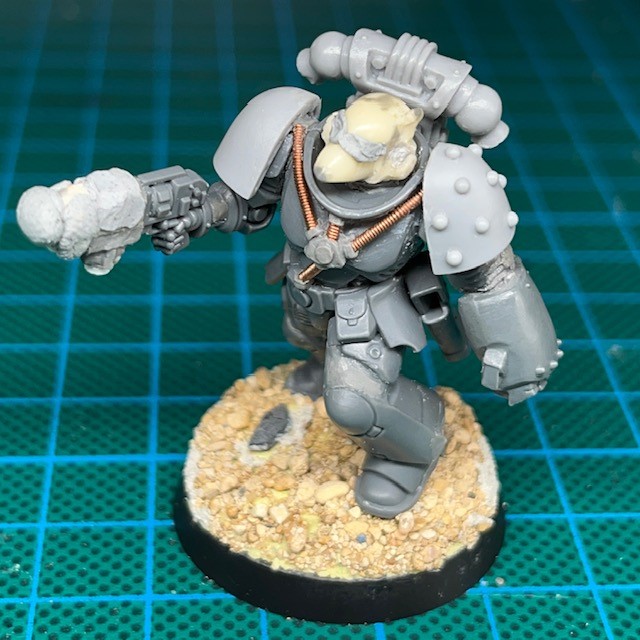
First, complete steps 1 – 15 of my LED eye lens tutorial to assemble the base, battery holder and head of the miniature. Once you have done this, you should have a partially assembled miniature as seen in the image below. Now proceed to step 2 of this tutorial.
2. Cast Plasma Weapon In Resin
You will now need a resin plasma gun for this project. I recommend using polyurethane resin to cast your own, as discussed in my resin casting tutorial. However, if you don’t want to cast your own, then you might also consider purchasing a third party resin plasma gun, or 3D printing with a semi-transparent material. Please note, this tutorial will not work with a plastic plasma gun, as plastic is much too opaque.
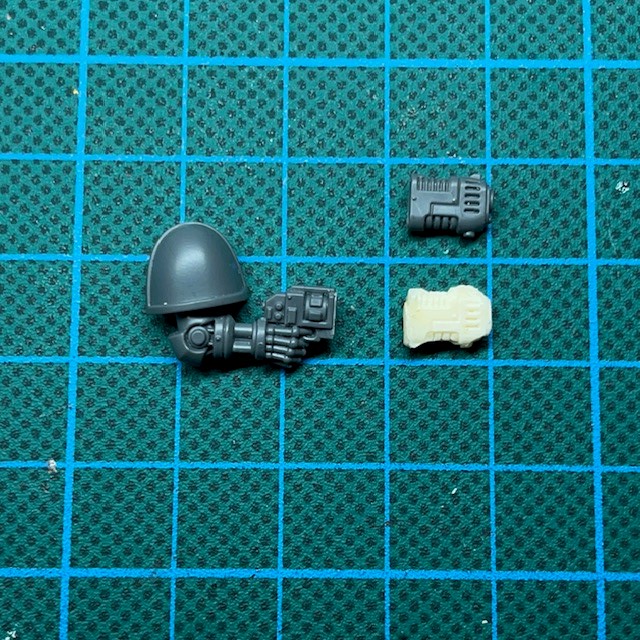
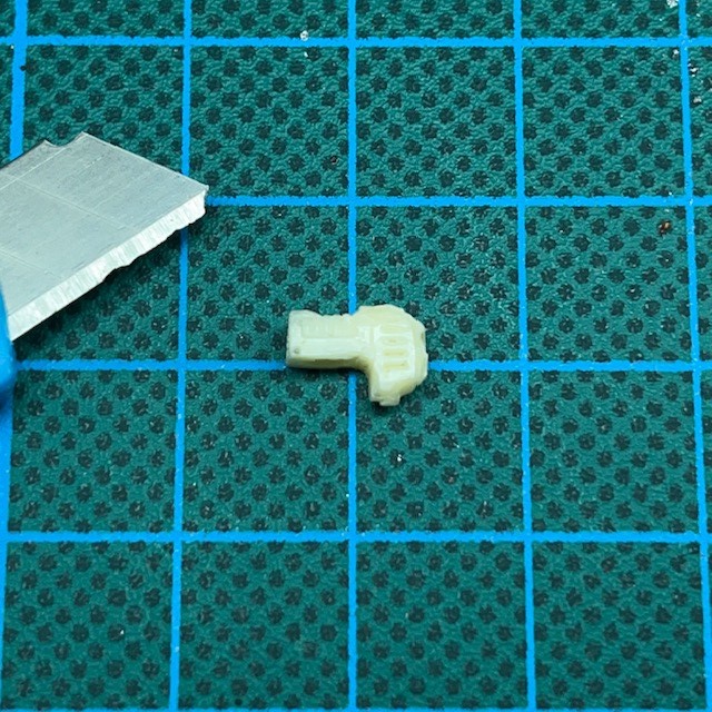
If you are casting your own plasma gun, then you generally only need to cast a copy of the front part of your weapon, so long as that includes the plasma coils and muzzle, as shown below. Make sure you put the rear half of the plasma gun somewhere safe as you will need that again later.
3. Drill Barrel, Remove Excess Resin And Install LED.
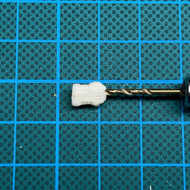
Drill out the barrel of the plasma weapon using a drill bit with a diameter that matches the diameter of the muzzle. This is to allow the LED light to shine out of the barrel. This hole should extend all the way through underneath the coils.
Now cut away the bottom of the plasma gun immediately below the coils, as shown in the image below. This is to provide space to insert the LED. Detail on the the plasma weapon that is removed at this stage can be resculpted later with modelling putty. The area of removed resin should be high enough that it crosses into the hole you drilled for the barrel, but not high enough to touch the coils.
4. Select LED And Solder Wires
Select the LED you wish to us and a corresponding resistor. If you are not certain how to do this then please see my designing LED circuits tutorial. I recommend the TruOpto 1.8mm LED range as they have the perfect brightness and form factor for this type of effect. Whichever LEDs you are using, make sure they are compatible with the voltage of the battery, which is 3V in the case of the coin cells used here.
If you are duplicating this model exactly, then I used a TruOpto OSPG7331A-KL 1.8mm Green LED and a 10Ω resistor (any brand will do) for the helmet eye lenses, and an identical LED and resistor combination for the plasma weapon. The colour of LED you choose for plasma is entirely down to personal choice and the aesthetics of your army.
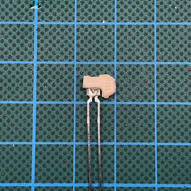
Once you have selected your LED, dry fit it underneath the power coils, as shown in the image below. The hemispherical lens on the top of the LED should fit into the barrel hole you drilled under the coils. This means that the majority of the light from the LED will be directed into the coils.
Remember you can hold a coin cell battery between the legs of the LED at this point to get an idea of what the glow effect will look like. If you find it is not as bright as you’d hoped then you can use a circular file or slightly larger drill bit to carefully widen the barrel hole and reduce the amount of resin underneath the coils. Unfortunately, if you breach the coil at this step then you can’t repair it without ruining the effect, so proceed with caution! If you do make any mistakes that break the surface of the coil then I’m afraid you’ll need another resin plasma gun and will have to complete step 3 again…
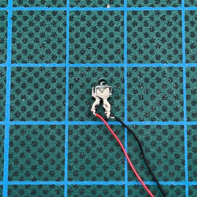
Next you need to cut the legs off your LED and attach wires as show in the image below. As mentioned in the LED Eye Lens tutorial, I recommend 26AWG / 0.45mm diameter wire as the optimum size (which can be purchased here). Remember that it’s useful to colour code your wires so you can remember which is the positive terminal and which is the negative terminal (red and black respectively in the image below) as this will make it easier when connecting the wires to the battery later. Make sure your strands of wire will be long enough to pass through the model and connect to the base.
It’s best to solder the wires to the LED as quickly as you can, since soldering very close to the LED like this can sometimes cause heat damage and stop it functioning correctly. You can briefly test the LED for damage after soldering by holding a spare coin cell between the wires.
Once you have connected the wires, use two small dabs of superglue to fix the LED into the resin plasma gun in the same location that you performed the dry fit earlier. The superglue should be applied either side of the LED lens, but not directly on top of it. Once the superglue has dried, use a small amount of modelling putty to further secure the LED and start to restore the basic shape of the plasma gun, as shown below.
Now solder the resistor for the plasma gun LED to the circuit in the base. One end of the resistor should be connected to the switch at the same point that the positive wire for the helmet LED is attached, as shown in the image below. The other end of the resistor can remain unconnected for now.
5. Drill Holes For Wires And Solder Connections
Now drill a hole through the plastic rear of the plasma gun, the arm and torso of the model and feed the wire through, as shown below. I find the easiest way to drill through arms is to drill two separate holes, one from each end, and meet in the middle. You may also find it helpful to cut the arm in strategic places such as armour joints. This should make drilling through the individual parts easier. The advantage of cutting at the joints is that the cut should be less noticeable when you glue them back together. Any damage to the gun or arm caused by the drilling can be repaired later with modelling putty.

Feed the wires from the plasma gun LED through the existing holes in the miniature’s torso and legs, and then solder them on to the circuit in the base. The positive wire should connect to the unsoldered end of the resistor that we just attached, while the negative wire should be soldered onto the negative battery terminal, as shown in the image below. If you have done this correctly, the two LEDs will now be connected in parallel.
6. Attach Remaining Parts Of Plasma Weapon
Use superglue to attach the resin part of the plasma gun to the plastic rear of the weapon. Once the glue has dried, using modelling putty to resculpt the lower half of the plasma weapon and fully conceal the LED. It can be a good idea to hide the legs of the LED by sculting an ammo ‘fuel cell’ hanging from the bottom of the weapon, as shown in the image below. The circular base of the fuel cell is made from the end of a plastic rod. Make sure that you also use the putty to fill in any gaps between the two halves of the gun.
7. Assemble Model
Now you need to glue the rest of the model together. Once you have done that, attach the finished model to the base. I find the best way to do this is to put two small balls of modelling putty under the model’s feet, press it into the putty so it’s standing up, then wait for the putty to cure and harden before proceeding further. This helps to make sure the model is attached to the base in the correct pose and position before going on to hide the rest of the wires and connections. Any slack in the connecting wire should be curled up under the model on the base.
Test the circuit again at this stage, just to make sure you haven’t accidentally damaged any of the connections.

8. Conceal Wires In Base And Test LED
Once the putty and/or glue applied in the previous stage has dried, you can now hide the battery holder and any spare slack wire under a layer of putty or filler. Be sure to not get milliput on the battery itself, and to leave the sliding part of the switch exposed so you can still operate it. Once the putty covering the battery holder is dry, you can add texture to the base if you wish (e.g. PVA and sand).
This is also the point to fill in any gaps around the neck with modelling putty, as well as repairing any casting defects on the helmet or accidental damage to the legs and torso that may have occurred during drilling. It can also be helpful to turn the LED on at this point and check for any light escaping any gaps around the edge of the torso, for example.
If the LEDs are still functioning, excellent work, you may now proceed to the next step. If they don’t work, this is the point to back-track and start fault finding. Check all connections that you have soldered so far. A digital multi-meter with probes is helpful for this.

9. Prepare Miniature For Undercoating
We’re almost there now. The next step is to prepare the miniature for spray undercoating.
During spray undercoating, make sure you cover the helmet eye lenses, plasma coils, gun barrel and any other glowing area with blu tack (or similar) so that they don’t get spray paint on them! If you are spraying from underneath then you will also want to cover the battery and switch during the spraying process.
You can see the model prepared for spraying in the image below. Once you have undercoated the model, the blu tack can be removed. You may find this easier with a pair of tweezers.
10. Paint The Miniature
Now paint the model to your tastes, taking care to avoid the eye lenses, plasma coils and barrel. What you may like to do is apply a thin shade of paint to the plasma coils so that they have a bit of depth even when the LED is switched off. As long as you are careful and apply a thin coat, this will not dim the LED effect. In the “before and after” images shown below, I have applied a coat of Citadel Biel-Tan Green diluted approximatley 50:50 with water.

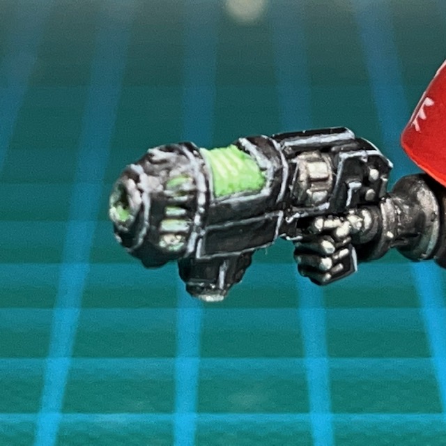
And that’s it! If you find the light is leaking through in any area it shouldn’t, especially from the helmet, then an extra coat of paint will normally cover that up. I hope this tutorial was useful! Please do tag me on social media so I can see you finished LED miniatures, or buy me a coffee below!
Enjoyed this tutorial? Buy me a coffee!

All these tutorials are entirely free; the only payment I really need is seeing everyone’s awesome LED armies on the battlefield! Having said that, if you found these tutorials useful and you’d like to buy me a coffee to say thank you (or donate towards the website fees so I can continue to post tutorials on this ad-free website) then please click the button above. Thanks very much in advance!
