


Welcome to my guide to working with LEDs and miniatures. In this tutorial I will discuss the principles behind selecting LEDs and designing your circuit. The Advanced Tutorials discuss the actual process of inserting the LEDs into miniatures, what I will be discussing here is the process of planning and ordering what you need for the project. I’m going to assume you have a basic idea of what an electronic circuit is, but otherwise I’ll attempt to start from the basics. This is the updated February 2024 version of this tutorial. If you would like to read the original version from July 2018, it is archived here.
1. How many LEDs?
First, how many LEDs are you going to use? This will depend on which parts of the miniature you are planning to illuminate. Try not to get carried away until you’ve had a bit of practise; I’d recommend starting with just one LED in your first model. If you’re determined to do more on your first go then please make sure you read the rest of this guide before making your mind up.
Designer’s Notes: The Philosophy of LED miniature design!
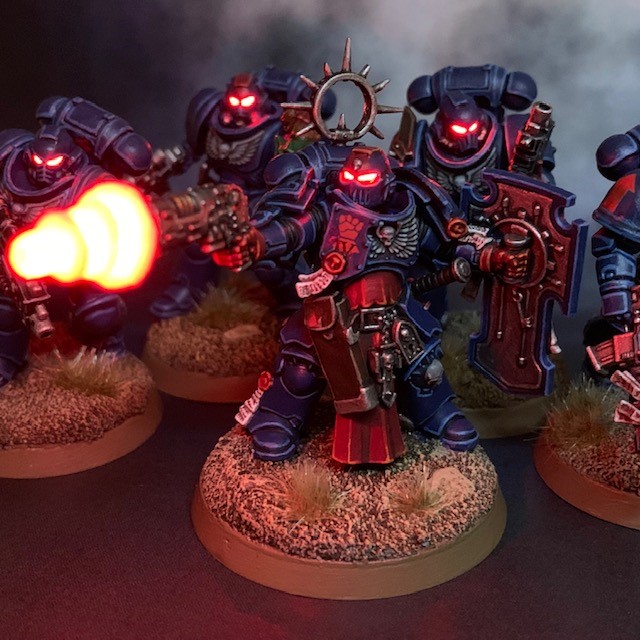
LEDs can make your miniatures look awesome, but not if you overdo it. When deciding where to put LEDs, try and think about the lore and artwork. For example I’ve put LEDs in the eye lenses of Space Marine helmets, because these are often described as glowing in the lore, or pictured with a sinister glow in artwork. But I wouldn’t put LEDs in the eyes of an Ork Nob, for example, as these are never described as glowing. An Ork Weirdboy on the other hand…
I find the best LED effects are almost like ‘sleight of hand’ magic tricks – people are left wondering how you’ve done it! If you have visible wires and giant batteries concealed in oversized bases, then it’s really obvious how it’s done and is less impressive. But if you can hide the electronics in such a way that at first glance the model still looks like the original miniature, only with awesome glowing eyes/guns/whatever, then that is what will capture people’s attention.
I have an article discussing the design philosophy of LED miniature design in more detail here.


2. Where do I buy LEDs?
There are plenty of places to buy LEDs and other electronic components online. You’ll certainly be spoiled for choice on eBay, and indeed Amazon (I have an Amazon shop with manay recommend electronic components and consumables here). There are also dedicated electronics supplier that you can buy from directly. My personal favourite is Rapid Electronics. You’ll need to create an account, but they have a great selection, lots of technical information on your LEDs (which you’ll need for part 3 below) and really fast delivery. Other excellent and reputable UK-based suppliers are RS and Farnell.
One of my preferred types of LED for use in 28mm infantry models – and an excellent starting point for your first LED miniature – are these TruOpto miniature 1.8mm LEDs. They come in a variety of colours and are comparatively quite bright. Make sure you double check the forward voltage though, as it varies for these LEDs depending on colour. Other components, such as batteries, resistors and switches are also available from Rapid Electronics. My Advanced Tutorials link to my preferred versions of these components.
If you’d like someone else to do the design and component selection for you, then it is also possible to buy premade miniature LED kits. My preferred supplier for these is Small Scale Lights. They have excellent service and a great range of products. I have a short tutorial for using their 32mm/40mm base lighting kit here.
3. Designing your circuit
Once you know how many LEDs you want and what their properties are it’s time to design your circuit. If you only have a single LED then this is easy. The anode of the LED can be connected to the positive side of the battery and the cathode to the negative side. If you don’t know what I mean by ‘anodes’ and ‘cathodes’, then don’t worry I’ll explain more about this later.
If you have multiple LEDs then they should be connected in parallel. Parallel means that all the anodes are connected to the positive side of the battery and all the cathodes are connected to the negative side. This means that each LED is in a separate “branch” of the circuit next to each other, and the electric current from the battery can simultaneously run in “parallel” through each branch (hence the name). The other way to connect electronic components is in series, which would mean the cathode of each LED would be connected to the anode of the next one, one after the other in a chain. LEDs should not be connected in series as they will not work correctly like this.
Regardless of how many LEDs you have, every LED in the circuit will need a resistor connected in series with that individual LED. This means that the resistor should be either between the LED anode and the positive side of the battery, or between the LED and the negative side of the battery, although it doesn’t matter which. Resistors help to protect the LED from excessive current and extend its working life.
So how do you know what value of resistor you need? You can calculate this manually, but it’s easier to use this website to calculate it for you: https://ledcalculator.net/
The site contains useful links to interesting information on LEDs if you want to do some further reading, but for now let’s concentrate on the information the circuit designer asks for. It’s going to need to know the following:
Power Supply Voltage: The total voltage of all the batteries you are using in the model (see section four below). If you’re following my tutorials then this is likely to be 3 volts.
LED Voltage Drop: Also known as “forward voltage” or “forward bias voltage” and often abbreviated as Vf, this is the voltage your LED is designed to operate at. Sometimes Vf (typical) and Vf (max) values will be given. Use the former in this calculation. LEDs are too compact to have this information physically on the product, but the information should be available from the supplier. If using Rapid Electronics, click the ‘Technical Details’ tab on the product page for your LED. Exceeding the Vf (max) will destroy the LED very rapidly, if not instantaneously.
LED Current Rating: Also known as “forward current” and often abbreviated as If or If (max), this is the amount of current your LED will draw from the battery. Make sure you enter the value in mA (milliamps).
Number of LEDs: This is the number of LED you have in your circuit. If it’s just one, then enter ‘1’. If you have multiples of the same LED, then enter the number of LEDs you have. If you have different types of LEDs in the same circuit, you’ll need to enter their details separately one at a time.
The website will then show you how to wire your circuit and tell you what value of resistors you need.
I’d also recommend a switch for your miniature LED circuit. If you don’t include a switch, then you will need to take the battery out when the miniature is not in use. A single switch can be inserted into your circuit on one side of the battery, connected to either terminal, it doesn’t matter which. I talk more about placement of switches in the Advanced Tutorials. Generally you’ll need a small switch, I’d recommend searching for ‘miniature’ switches to find switches that are small enough. Here is an example of miniature slide switches on Rapid Electronics.


4. Where’s the power coming from?
Once you know how many LEDs you’re using and how they’re going to be arranged, you’ll need to consider your power source. If you want your miniatures to be usable in game then you’ll be using batteries as your power source. As a general rule each LED will require 3V, so that’s one 3V battery or two 1.5V batteries. Although I’ve put this section fourth, in reality the number of batteries that you can fit into a model is often the limiting factor. There’s no point in designing a circuit that needs five batteries if you can only fit one in the miniature! If you have designed a parallel circuit then you’ll only need voltage equivalent to the requirements of your LED with the highest forward voltage. This is because LEDs in a parallel circuit simultaneously “share” the voltage.
In terms of what batteries to use, you can use AA or AAA batteries in larger models if you have the room, but for 28mm scale single models often a coin cell is a better choice. These have a number of advantages; they’re flat and circular so they are easily concealed in a standard miniature base. Also, they are available in 3V iterations, rather that 1.5V, so take up even less space. I particularly recommend CR2032 batteries. These are intended for use as clock batteries in computers and have a high milli-ampere hour (mAh) rating. The higher this number, the longer the battery will last. Also, very compact batteries holders are available for this type of coin cell battery (I talk more about these in the Advanced Tutorials). If you conceal the battery holder in the base of your model facing downwards, then the battery will be very easy to change or remove from underneath when not in use.
5. Soldering LEDs
Finally, here’s a couple of tips for working with LEDs.
- LEDs are diodes, so they care about polarity, i.e. which way they are connected to the battery. The longer leg is the anode (positive) side, and the shorter leg is the cathode (negative) side. Many LEDs also have a flat edge on their case above the cathode to further help with identification. Here’s a helpful visual summary. The anode should be connected to the positive side of the battery (normally indicated by a ‘+’ symbol) and the cathode should be connected to the negative side (normally indicated by a ‘-‘ symbol).
- LEDs can be damaged by excessive heat when soldering. If your soldering iron has a temperature setting then I’d recommend not going above 300 degrees C, unless you have specific information from the manufacturer that they can withstand a higher temperature.
- A lot of LEDs have little notches near the top of their legs. Try not to cut or solder above these if you can help it, as you’ll increase the risk of damaging the LED.
- Most LEDs are highly directional, and will be brighter when viewed from certain angles than from others. Make sure they’re pointing the right way when they go into the model.
- Don’t be afraid to cut or file down the case of the LED. It’s just plastic and has no effect on the operation of the LED itself. Just make sure you don’t disturb the p-n junction (the silver bit shown in the diagram linked to under the first bullet point).
So that’s about it for LED circuit design. Don’t forget you can buy components from my Amazon shop. Now you know the basics, hopefully you’re feeling more confident to tackle the Advanced Tutorials.
Enjoyed this tutorial? Buy me a coffee!

All these tutorials are entirely free; the only payment I really need is seeing everyone’s awesome LED armies on the battlefield! Having said that, if you found these tutorials useful and you’d like to buy me a coffee to say thank you (or donate towards the website fees so I can continue to post tutorials on this ad-free website) then please click the button above. Thanks very much in advance!
