


This is my tutorial for placing LEDs inside Space Marine helmets. The photos show this technique applied to a Horus Heresy Marine, but it can equally be applied to any Space Marine, or indeed any other model that you feel would benefit from glowing eyes. This is the updated February 2023 version of this tutorial. If you would like to read the original version from August 2018, it is archived here.
I strongly recommend reading through the entire tutorial before starting work, just to make sure you have the necessary skills and tools required and that you’re not going to run into an unexpected barrier halfway through. If you need to know where to buy tools and consumables for this type of project, I have recommendations here.
I have a separate tutorial about designing LED circuits, basic LED soldering and resin casting. This tutorial assumes you’ve either read these, or are familiar with the techniques discussed (or have settled on an alternative in the case of resin casting).
1. Select Battery
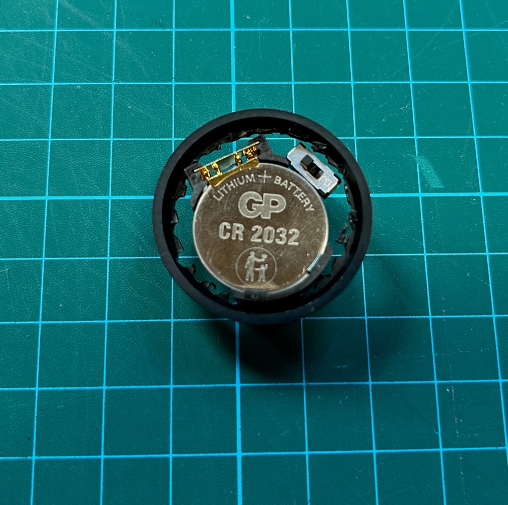
Start by selecting the type of battery you want to use. I prefer CR2032 coin cells. These are the lithium memory back-up batteries you find in PC motherboards, among other things. I like these because they last a long time, can power the brighter 3V LEDs and – most importantly – because they have a low profile that will fit inside a standard base for a 28mm-scale model.
You’ll also need to select a suitable battery holder. Many types are available and a selection are show below. Again, it’s important to pick one that will fit inside your base (possibly with a bit of trimming).
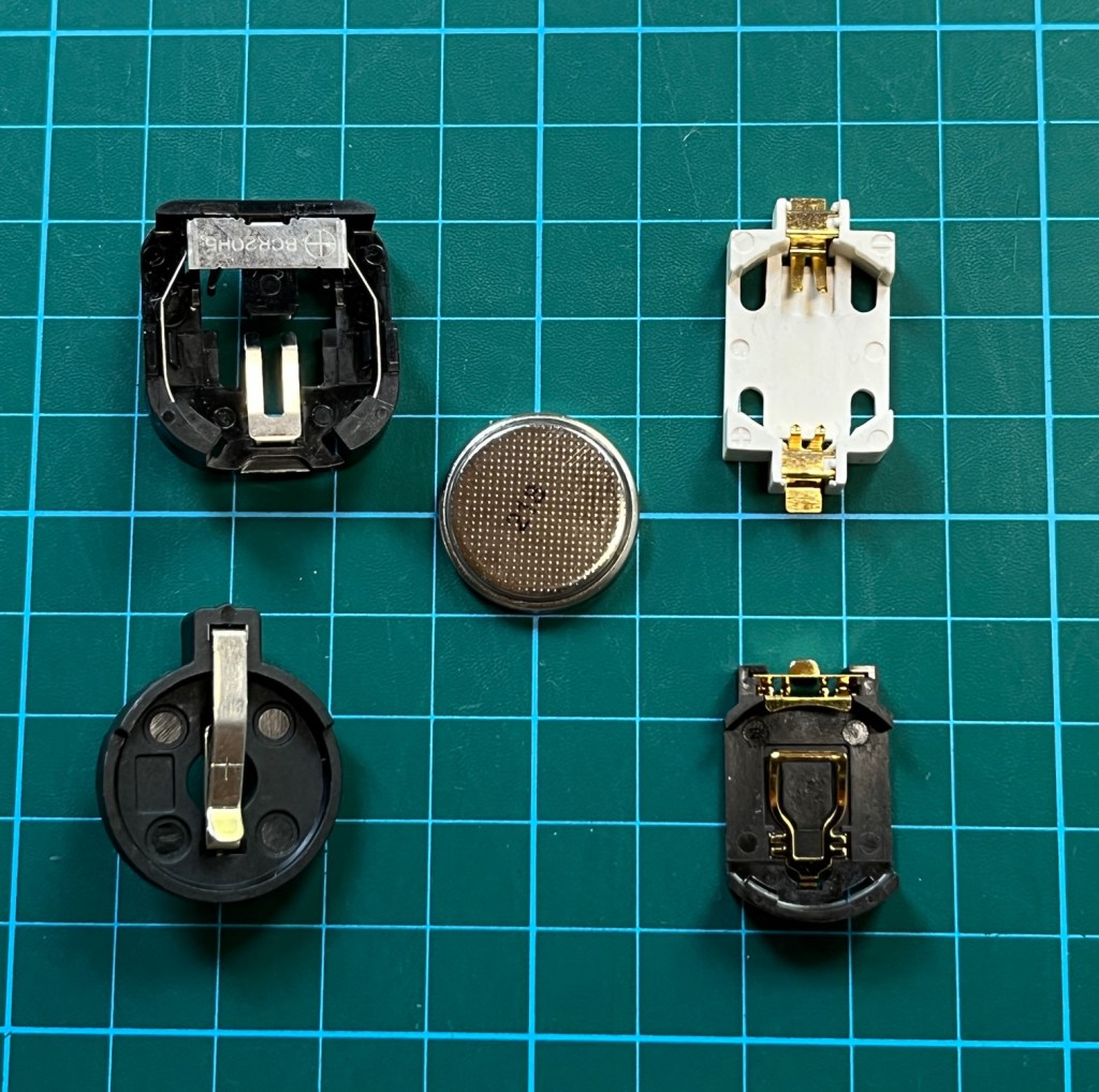
2. Select Battery Holder
Personally I like the catchy-named Multicomp Battery Holder SMT, 20mm, CH7410-2032LF (available from Farnell here), since it fits comfortably inside a GW 32mm base (the current standard Space Marine base) without any trimming. This is just personal preference, as long as your battery holder fits inside your base then you should feel free to use any brand.
To cut out the 32mm base, I find the best thing to do is to first drill a number of small circles in the top.
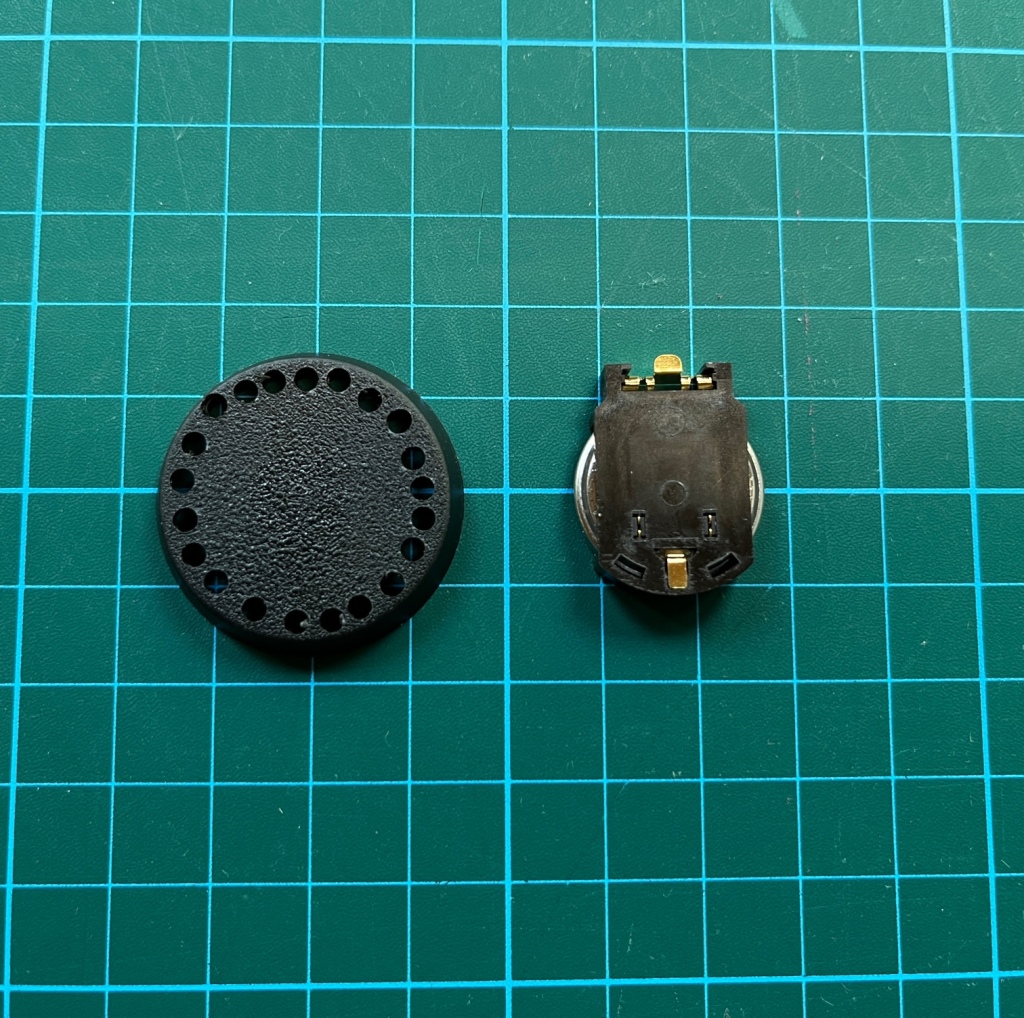
3. Hollow Out Base
Cut out the top of your base using a craft knife or similar to cut between the holes. I find this is easier than just cutting it with a knife from scratch. Just make sure you leave the rim intact. If you are using a smaller base size, such as 25mm, you may find you have to cut a bit of the rim away so the end of your battery holder can poke out. But you can always disguise this with basing material later.
Insert the battery holder into the base. Make sure the actual battery is inserted into the holder for this step. Position the battery holder so that the side that you insert the battery is face down (this will allow you to change it without disassembling the model) and so that the bottom of the battery holder is flush with the lower edge of the base. This should mean that when you put the base on a flat surface, it is level.
Please note that if you do not have the battery in at this step, you may later find that when you insert it, the battery and holder are not flush with the bottom of the base and your model will be wonky! This is especially true of battery holders with clips.
Generally I think it’s a good idea to include a switch which will let you turn off the LED when the miniature is not in use. The alternative is to remove the battery each time, but a switch is more convenient. PCB slide switches (available from RS here) will normally do the trick, but check the dimensions! A switch with a length of 5-10mm is ideal. These are sometimes called “sub-miniature” switches.
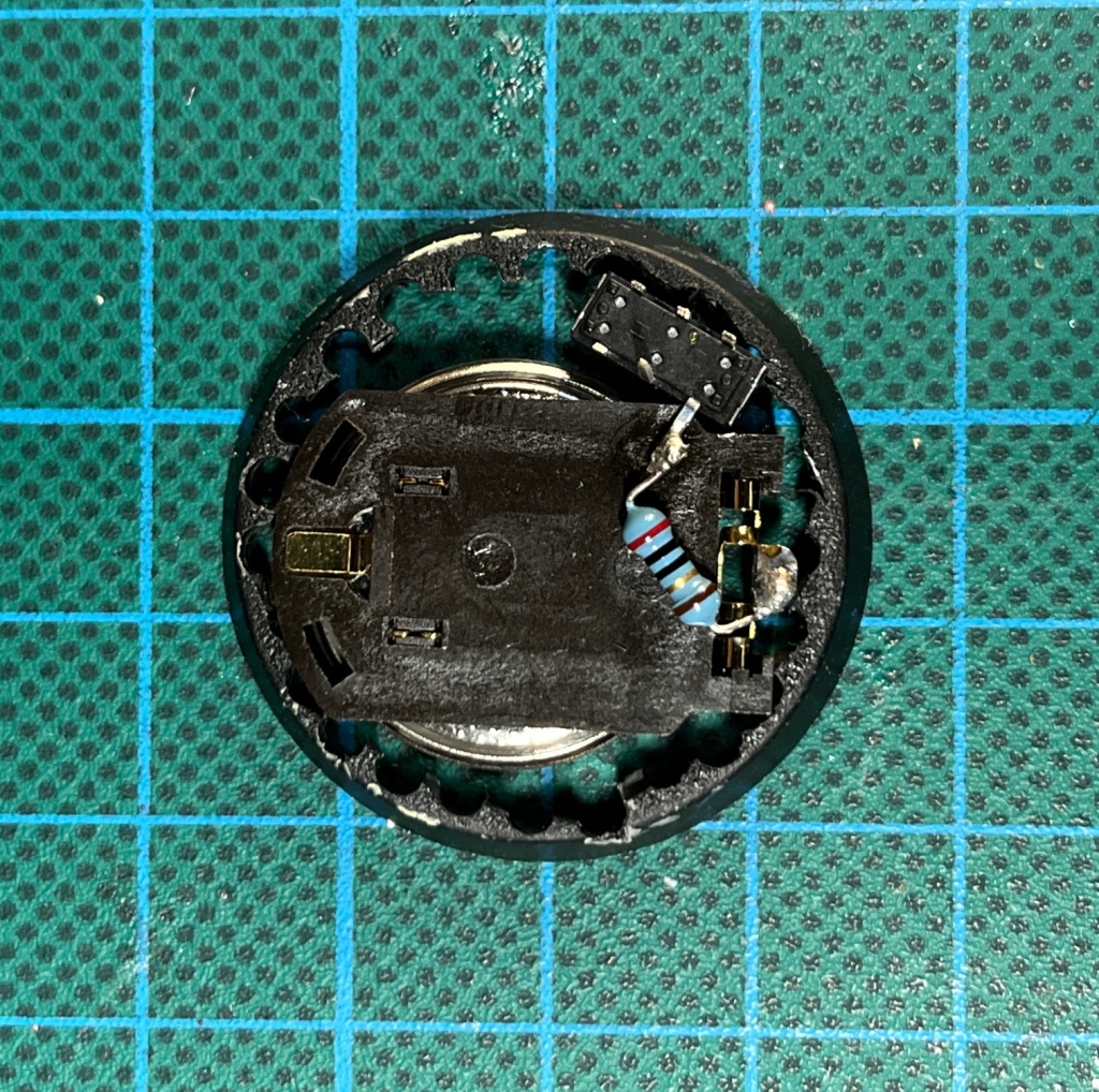
You will need to leave some room in the base to insert the switch to the side of the battery. In the picture below you can see I have left a gap in the top right.
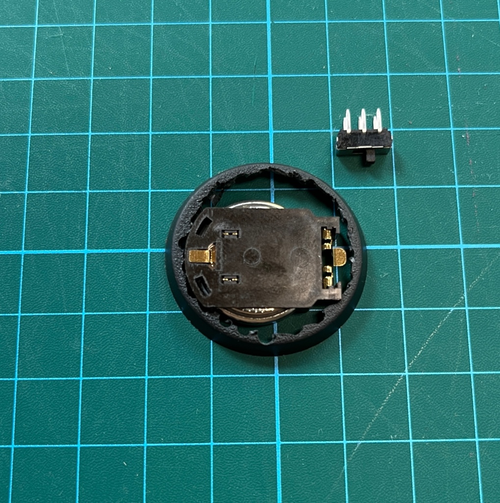
4. Insert Switch Into Base
Insert the switch into the base with the actual toggle that you will operate face down. This will mean that it is accessible from underneath the finished model. The switch can be in contact with the plastic battery holder, but try to avoid it directly touching the battery itself as this may cause a short circuit later.
5. Solder Switch To Resistor And Battery Holder
To hold the switch in place, simply solder one of the legs of the switch to one of the battery contacts using a resistor to bridge the gap. The resistor is an important part of the LED circuit as it protects the LED from excessive currents and increases its working lifetime. The resistor I am using for this model is a 20 ohm (¼W) as that is what the LED I’m using will need (resistors can be purchased here). As you can see in the image below, I’ve soldered it between one leg of the switch and the positive terminal of the battery.
Do not try and hold the switch in place with glue! These switches are not sealed against liquids and there’s a high chance the superglue will penetrate the switch and insulate the contacts when it dries, rendering the switch non-functional!
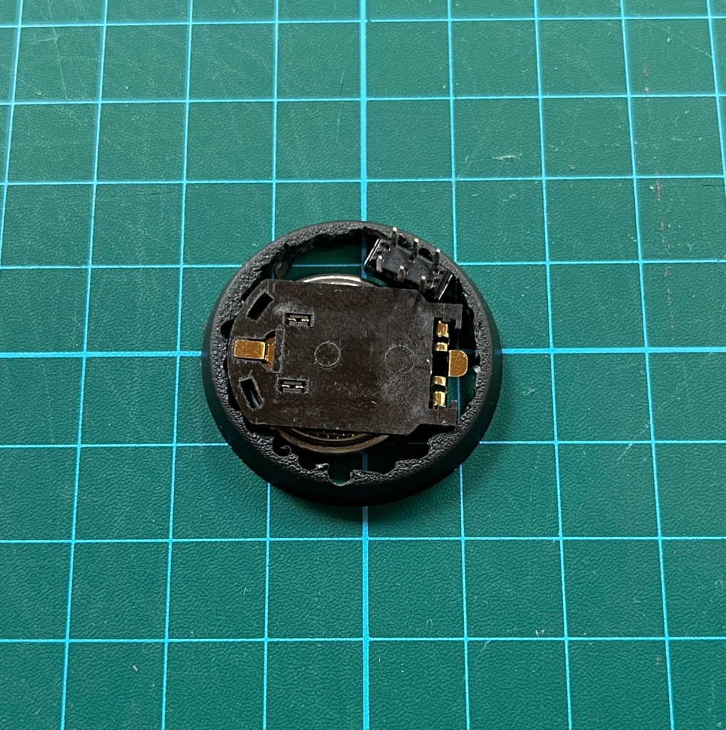
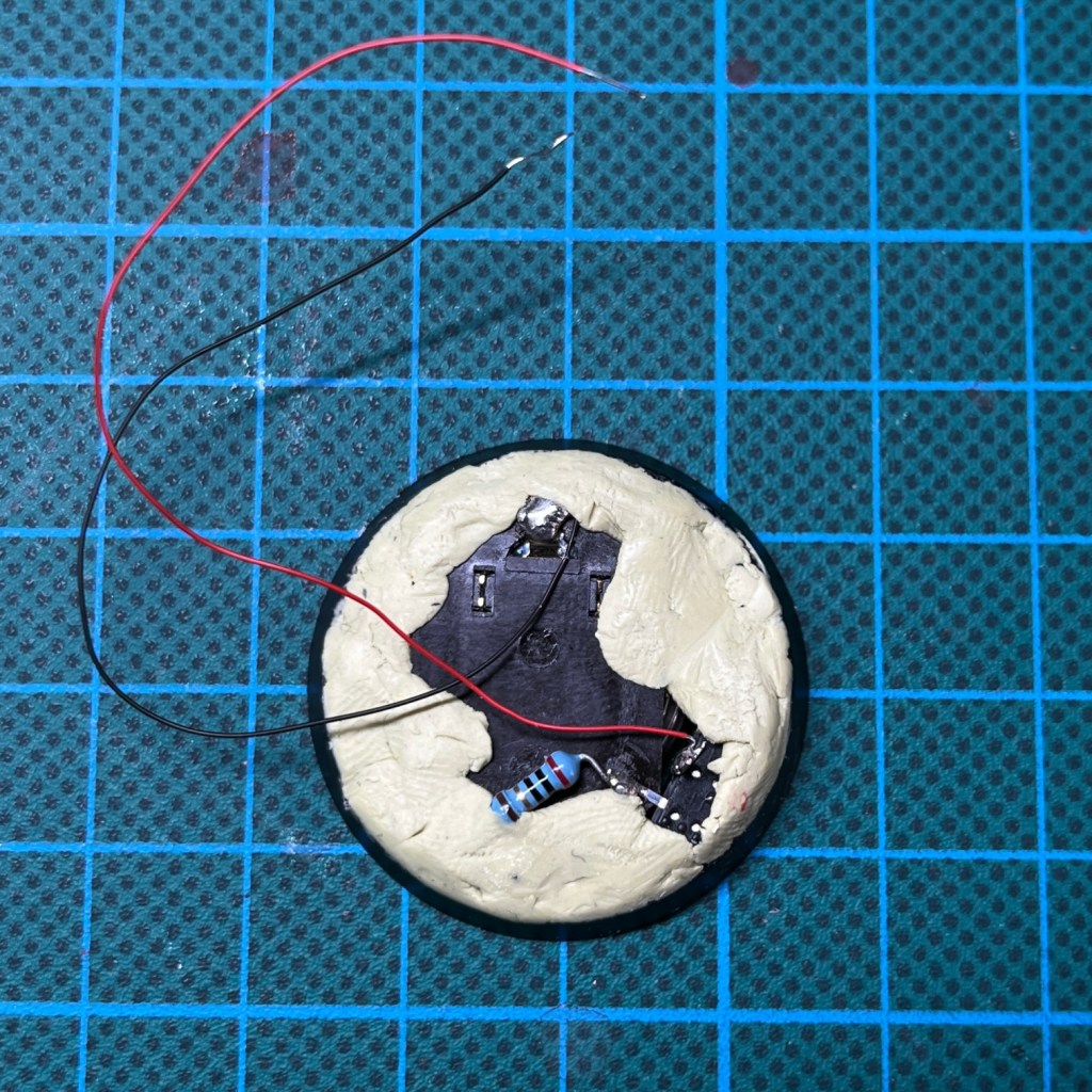
Once the switch is soldered in place, this is what the base should look like underneath. This is what you will see when you turn over your finished miniature. Both the switch and the battery will be accessible.
6. Add Wires For LED
Next you will need to add the wires that will connect the battery and switch to the LED (wire can be purchased here). You can either use insulated or enamelled wires, but do not use bare metal wires as the wires will end up touching later and you’ll get a short circuit. I recommend 26AWG / 0.45mm diameter wire as the optimum size. Two strands of wires this size will fit through a 1mm hole.
As you can see in the picture below, one of the wires is soldered directly onto one of the battery holder terminals, while the other is soldered to the switch. If your switch has more than two legs, make sure you have confirmed which two you are using. You can test this with a digital multimeter if necessary by operating the switch between its two positions and seeing which legs are connected. If you are using a PCB slide switch like the one in this tutorial, you will find adjacent legs on the same side are connected.
Polarity is important for LEDs, so make sure you know which wire is positive and which wire is negative. Use different coloured wire to indicate this if you think it will help, or cut them to slightly different lengths as a visual reminder.
You’ll want the two wires to be about a third longer than the intended final height of your miniature, just so you’ve got some slack to work with. Around 8cm each should work well for a Space Marine.
Never short circuit the wires or the battery holder terminals. Lithium-based coin cells can get very hot and potentially explode or start fires if the terminals are connected for extended periods.
At this point I tend to use modelling putty to fix the battery holder to the base, as this is easier than gluing. Milliput is ideal, and cheaper than Green Stuff or Procreate for this application. Don’t cover the terminals at this point, and remember we are not covering the bottom of the base with putty, as you want to leave the battery accessible from underneath so you can change it when it runs out. Once the putty is in place, it’s worth gently pushing the base down onto a flat surface to ensure the battery and switch are still flush with the bottom of the base. If you don’t check this, then the base may be wonky when the putty dries.
You can continue with steps 7 and 8 at this point, but make sure you leave the putty to set before proceeding to step 9.
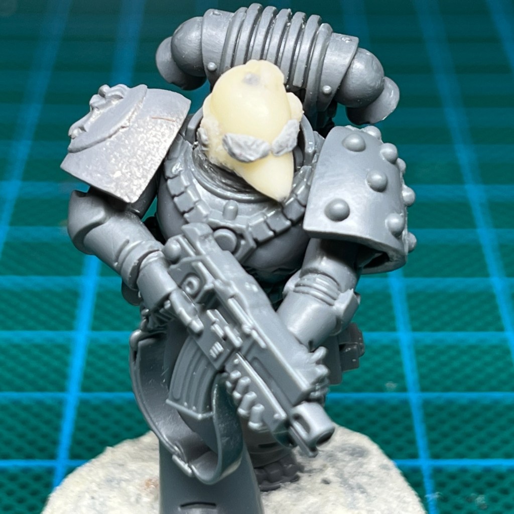
7. Hollow Out Miniature
If you’re using a model with a hollow torso, like the Space Marine pictured below, then you can go straight to step 8. If your model has a solid torso then you will need to drill a hole through the torso of your model, right down the vertical centre from the neck socket. It’s a good idea for the width of the hole to be slightly greater than the horizontal distance between the outside of the two legs of your LED. If the width is narrower then there is a risk the LED legs will be pushed together and short circuit.
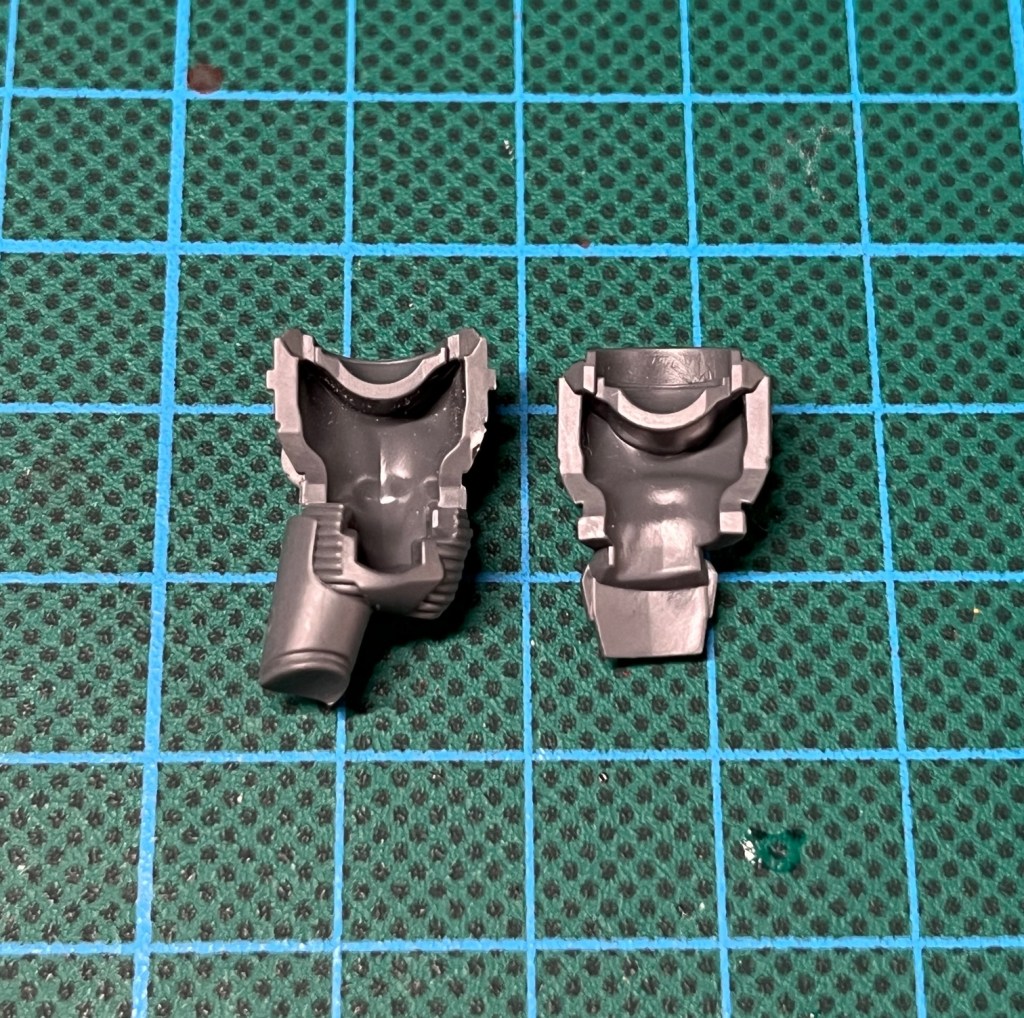
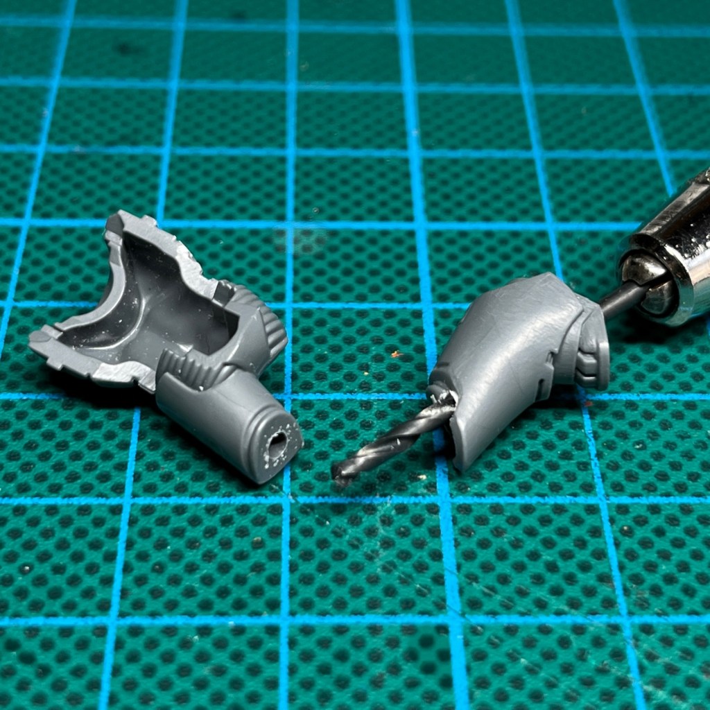
8. Drill Hole In Miniature Leg
Now drill a hole through one of the legs of your model. This hole should be wide enough that it can accommodate both of your wires side by side. Ideally the drill will enter through the base of one of the feet and emerge in the centre of the leg inside the torso. It can be tricky not to break the surface of the leg with the drill, but any mistakes like this can be covered with putty or filler later on. If your model has a leg supplied in two parts, as pictured below, then this will be the easiest to drill. If the model only has legs in single piece, select the straightest leg to drill.
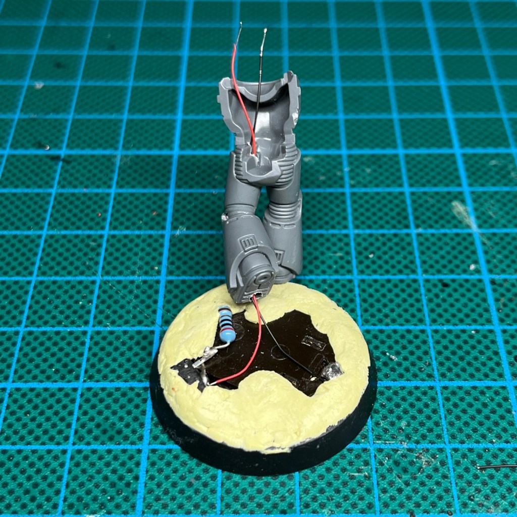
9. Feed Wires Through
Make sure the putty you used in step 6 has fully set. Now feed your wires through the legs and into the torso.
10. Drill Hole In Miniature Neck
If you have been working on a model with a hollow torso that did not require you to drill through it, then you may still need to drill a hole in the neck at this point. As mentioned in step 7, it is best if the hole in the neck is wider than the width of the two legs on the LED, so that the hole does not push the legs together and cause a short circuit.
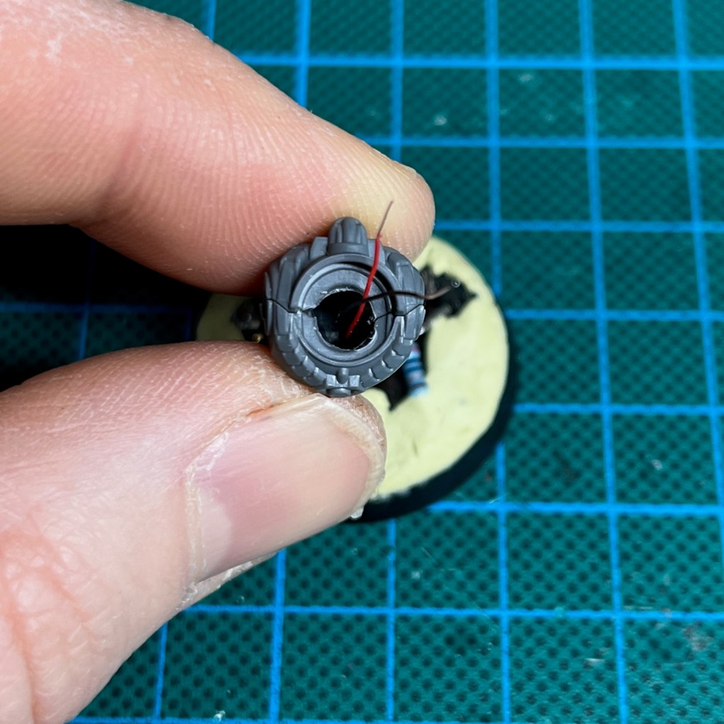
Some miniatures will already have a hole in the neck, and some will not. If you are using Horus Heresy Marines then the neck will initially look like this…

…so you will need to drill a hole like the one shown below. Don’t glue the torso together to drill the hole, just hold or clamp it tightly together while drilling. A 4mm diameter hole is an ideal size for the LED we are using in this tutorial.
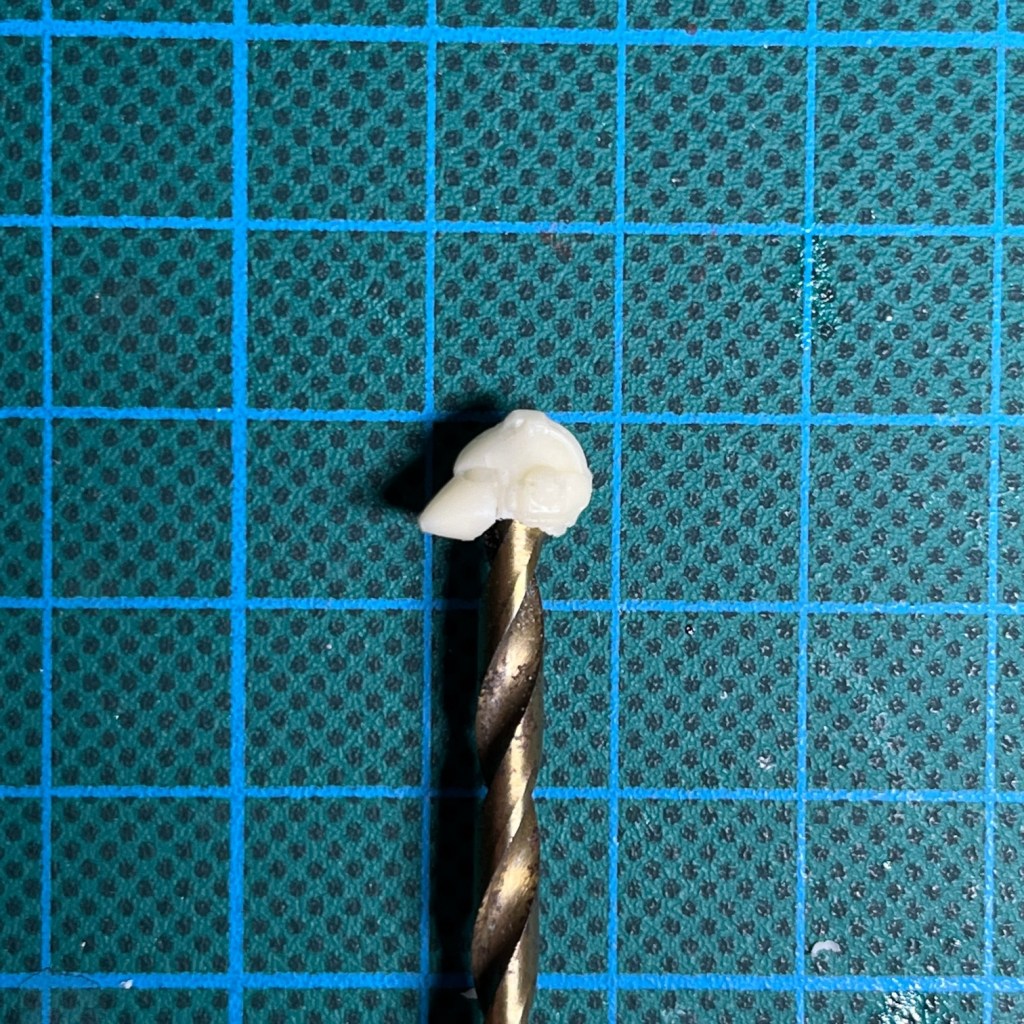
11. Select LED
Next you’ll need to drill a hole in the base of your Marine’s helmet that is wide enough to accommodate the LED. Don’t worry if your drill is so wide it destroys the ‘neck’ of the helmet, again this is something that can always be fixed with putty later. Remember that you can file down the edges of your LED slightly if you need to make it a bit smaller to fit in correctly, just so long as you don’t file all the way down to the p-n junction (the metal-looking bit inside).
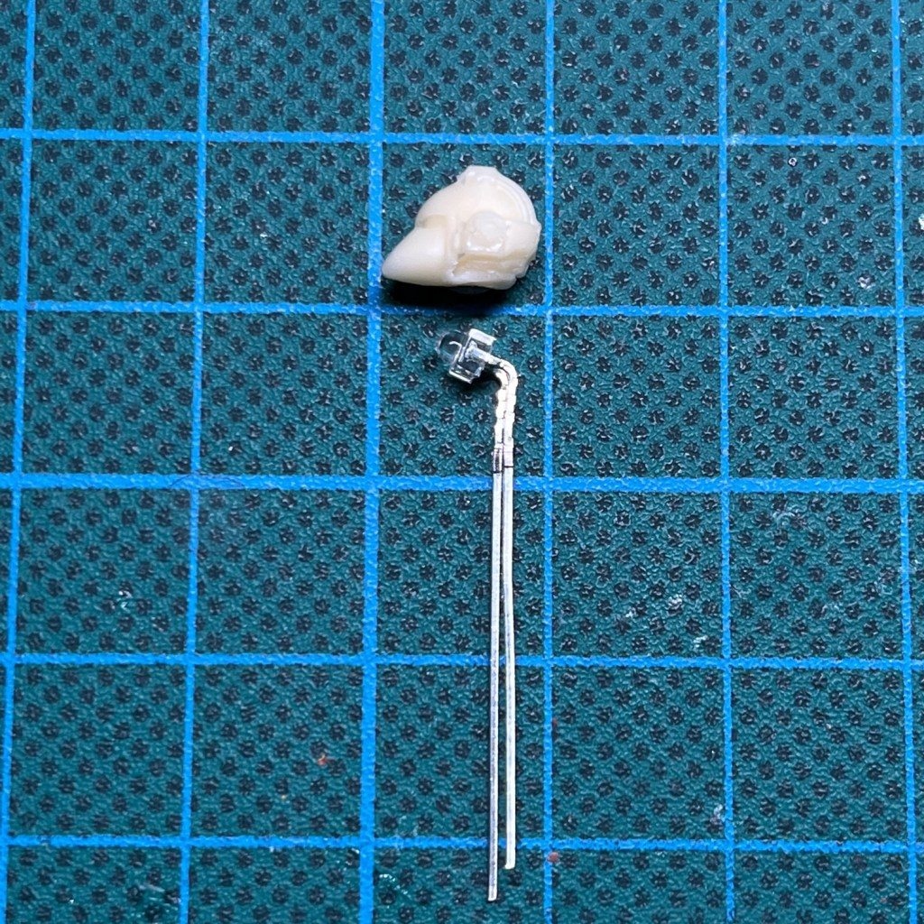
In my designing & ordering tutorial that I mentioned earlier, I explain that I prefer to work with 1.8mm LEDs. Below you can see a scale shot next to a helmet for reference; as you can see they’re the ideal size.
If you are duplicating my model exactly, then the red LED. that I using in this tutorial is the TruOpto OSHR7331A-KL 1.8mm Red LED, but blue, green, yellow, pink and white are also available. Whichever type of LED you are using, make sure they are compatible with the the voltage of your battery – 3V in the case of the coin cells used here – and that you are using the correct value of resistor. If in doubt, consulting my circuit design tutorial.
12. Hollow Out Miniature Helmet
As I’m working with resin helmets, I’ve drilled the hole to just behind the eyes. Since the resin is quite thin this diffuses the light nicely and allows the LEDs to shine through the eye sockets without actually having to drill them out. If you’re working with plastic or metal helmets, then you’re going to have to physically drill out the eye sockets with a miniature drill for the LED to become visible. Why I use resin and what the alternative options are is all explained in more detail in my resin casting tutorial, if you haven’t read that already.
I used a 4mm drill bit with this helmet. Make sure you start drilling in the very centre of the helmet’s neck, otherwise you may find yourself destroying the sides of the helmet. It can be good to have some spares on standby! A helpful technique is to start by drilling a 1mm hole, which is much more easy to position accurately. Then you can drill progressively larger holes centred on the 1mm hole until you reach 4mm.
13. Insert LED Into Helmet
Now insert the LED into the helmet, using a cocktail stick or pair of thin tweezers to help push it in if necessary (push on the LED itself rather than the legs so you don’t bend them too much in the wrong direction). LEDs tend to emit most light vertically rather than horizontally, so you’ll want to bend the legs so the top of the LED points directly towards the eyes of the helmet from the inside. The easiest way to achieve this is to hold the legs with a thin pair of pliers or tweezers directly under the base of the LED and bend the legs around that. The optimum angle is shown two pictures above in the image for step 11.
At this point it can be useful to simply hold a spare coin cell battery between the legs of the LED – remembering to observe the polarity – while you position it. Ideally the top of the LED will be between the eyes of the model. That way each eye is illuminated evenly. If the LED is at an angle then you can have one eye brighter than the other.
Once you are happy with the position of the LED, secure it with a tiny dab of superglue and/or a small amount of modelling putty at the back of the LED. Make sure the superglue or putty does not get between the top of the LED and the helmet’s eyes!
14. Prepare LED For Soldering
Trim the legs of the LED and the wires (although you’ll still want to leave a bit of slack as shown below) and secure them ready for soldering (I use blu tack to temporarily hold them in place). Double check you have the polarity correct at this point. Remember, the longer LED leg is always the positive (a.k.a the anode).
Re-read my tutorial on soldering LEDs if you’re not feeling confident at this point, paying particular attention to step 3 of that tutorial.
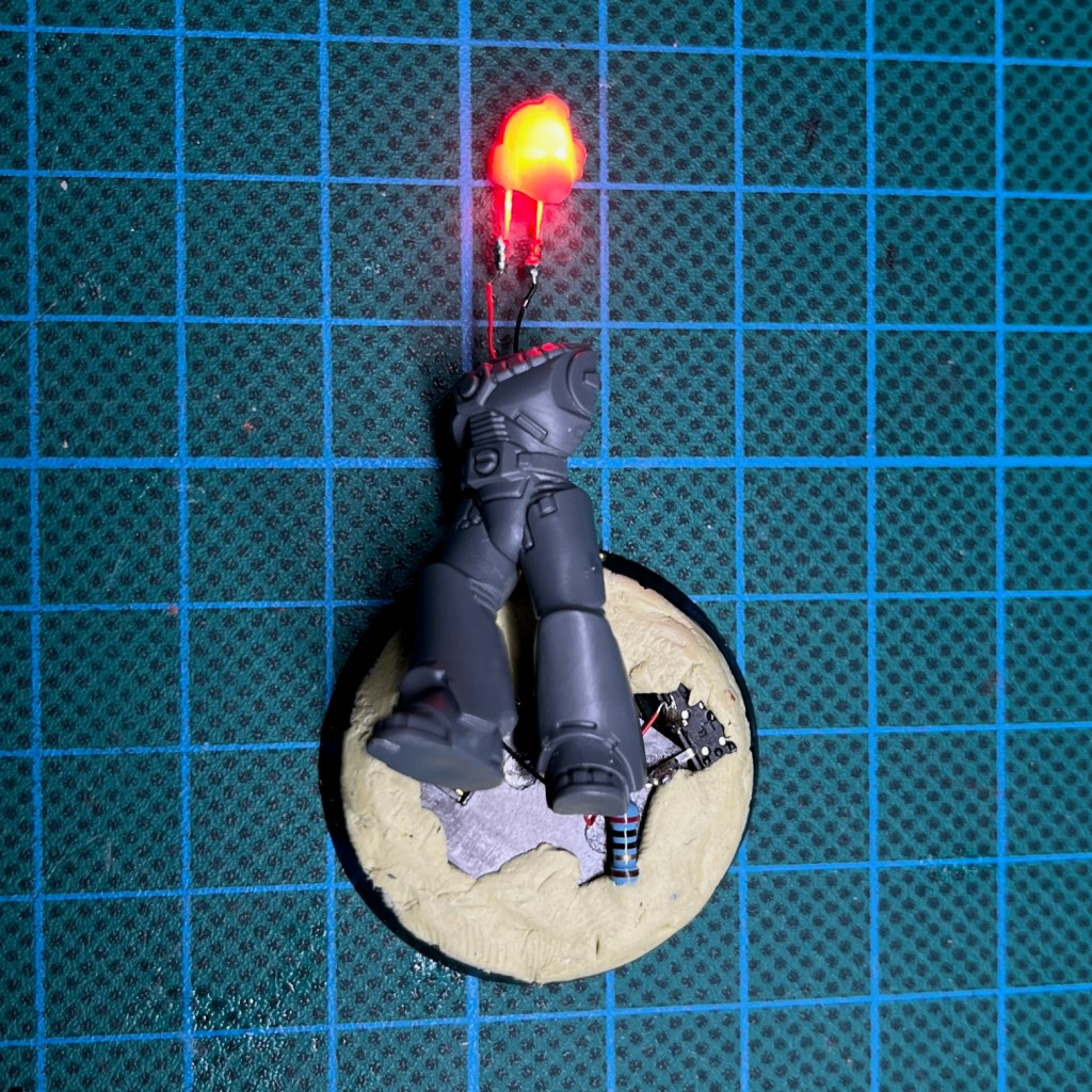
15. Solder LED To Wires
Now solder the LED legs to the wires! Once you have done this, operate the switch to check that everything works. The LED should now illuminate. It’s always worth checking at this point because having to take an assembled model apart to perform fault finding is a real pain! In fact it’s worth operating the switch again to check that everything still works after each of the following stages, just to make sure you haven’t caused any accidental damage or short circuits during final assembly.
If you’re working with a resin helmet then you’ll probably notice at this stage that the whole helmet glows rather than just the eyes. Don’t worry though, any areas that are painted will block the light – so we’re obviously going to paint everything except the eye lenses!
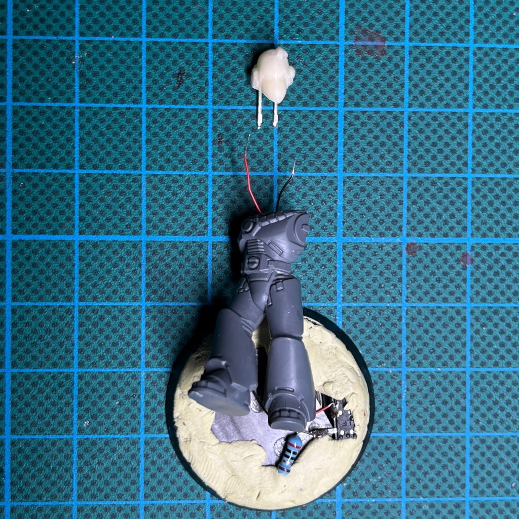
16. Assemble Model
Now pull the slack of the wires through the bottom of the foot and position the legs, torso and head how you want them arranged on the finished model. When you are happy glue them in place. Any excess wire should be coiled under the feet at this point.
17. Conceal Wires In Base
Once the superglue applied in the previous stage has dried, you can now hide the battery holder and any spare slack wire under a layer of putty or filler. Be sure to not get milliput on the battery itself, and to leave the sliding part of the switch exposed so you can still operate it. Once the putty covering the battery holder is dry, you can add texture to the base if you wish (e.g. PVA and sand).
This is also the point to use fill in any gaps around the neck with modelling putty, as well as any repairing any any casting defects on the helmet or accidental damage to the legs and torso that may have occurred during drilling. It can also be handy to turn the LED on at this point and check for any light escaping any gaps around the edge of the torso, for example.

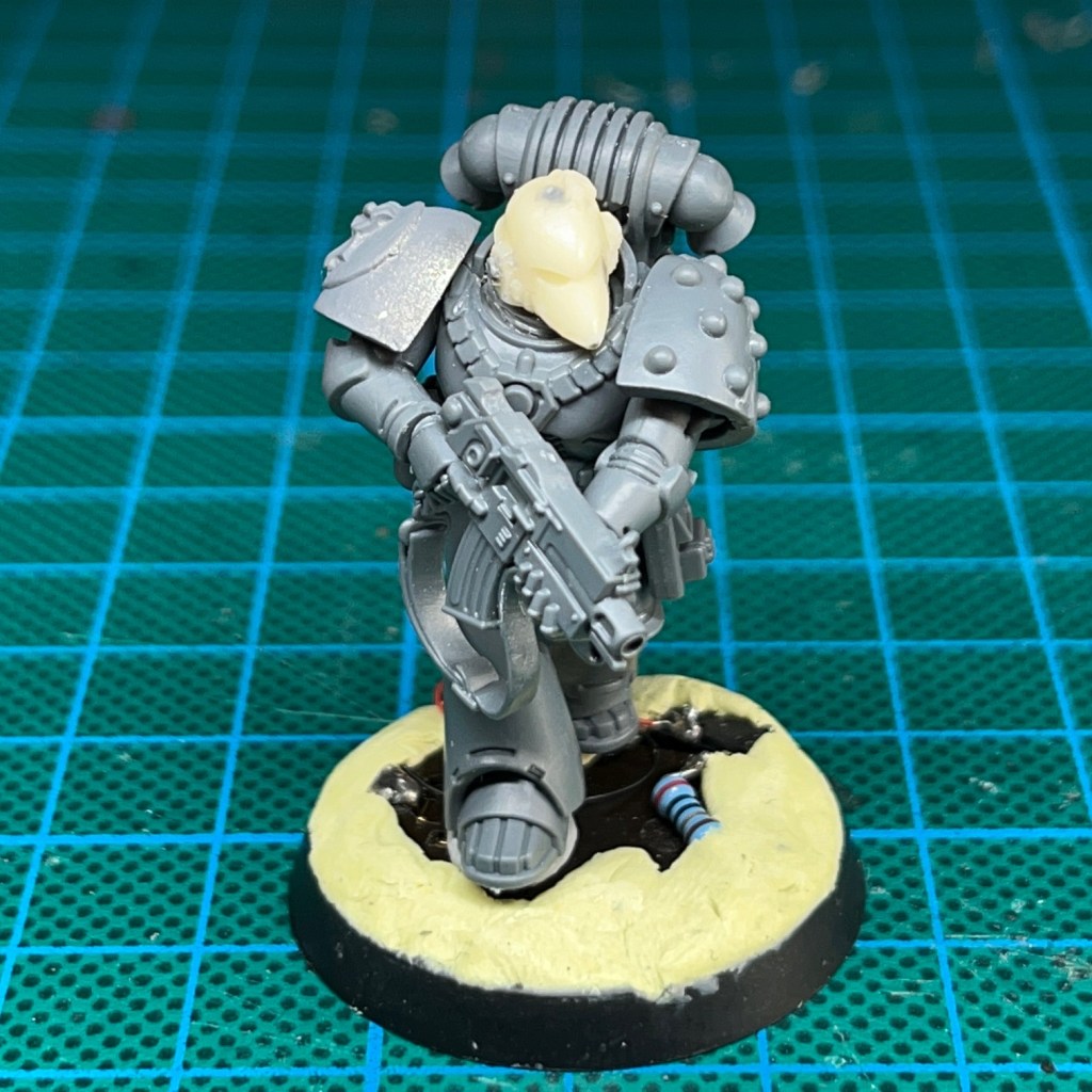
18. Prepare Miniature For Undercoating
We’re almost there now. The next step is to prepare the miniature for spray undercoating.
During spray undercoating, make sure you cover the helmet eye lenses with blu tack (or similar) so that they don’t get spray paint on them! If you are spraying from underneath then you will also want to cover the battery and switch during the spraying process.
You can see the model prepared for spraying in the image below. Once you have undercoated the model, the blu tack can be removed. You may find this easier with a pair of tweezers.
19. Paint The Miniature
Now paint the model to your tastes, taking care to avoid the eye lenses. And that’s it! If you find the light is leaking through in any area it shouldn’t, especially from the helmet, then an extra coat of paint will normally cover that up. I hope this tutorial was useful! Please do tag me on social media so I can see you finished LED miniatures, or buy me a coffee below!

Enjoyed this tutorial? Buy me a coffee!

All these tutorials are entirely free; the only payment I really need is seeing everyone’s awesome LED armies on the battlefield! Having said that, if you found these tutorials useful and you’d like to buy me a coffee to say thank you (or donate towards the website fees so I can continue to post tutorials on this ad-free website) then please click the button above. Thanks very much in advance!
