


This is the archived version of my LED Muzzle Flare Tutorial from June 2019. The most recent version of this tutorial can be found here.
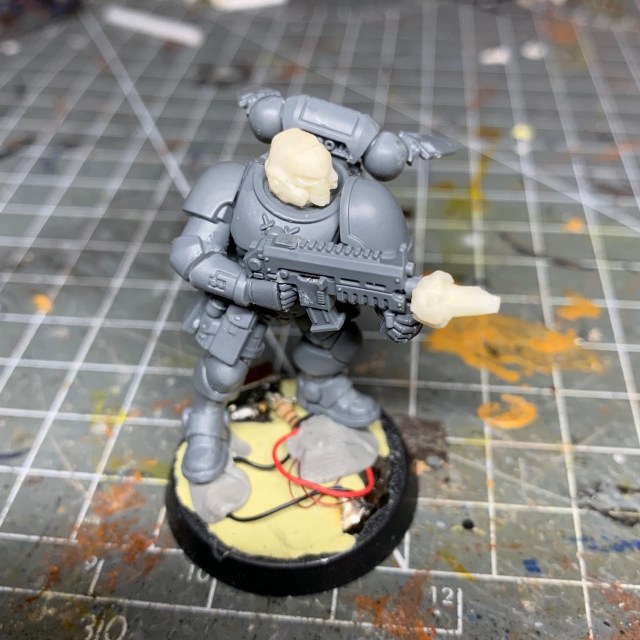
This is my tutorial for LED effect gun muzzle flares. The photos show this technique applied to a Reiver Primaris Marine with bolt carbine, but it can equally be applied to any other weapons that’s likely to have a muzzle flare.
I strongly recommend reading through the entire tutorial before starting work, just to make sure you have the necessary skills and tools required and that you’re not going to run into an unexpected barrier halfway through. If you need to know where to buy tools and consumables for this type of project, I have recommendations here.
I have separate tutorials about designing LED circuits, basic LED soldering, resin casting and LED eye lenses. This tutorial assumes you’ve either read these, or are familiar with the techniques discussed, especially the eye lens tutorial, which is a starting point this tutorial builds from. Casting skills are essential (although this tutorial does discuss them in detail) as the muzzle flare effect relies on the availability of muzzle flares cast in resin.
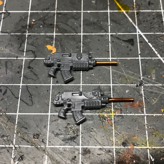
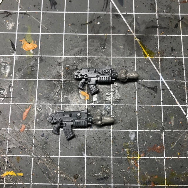
1. My LED tutorials normally start with the electronics, but as this tutorial requires the design and casting of custom components (the resin muzzle flares themselves), I’m going to start with that instead. First you need to sculpt the muzzle flares out of something like Green Stuff or ProCreate putty.
I always sculpt directly onto spare copies of the weapon, just to get the flare the correct size. You won’t actually be recasting the whole weapon, only the muzzle flare. It is just a good way of ensuring the size of the flare isn’t too big or small. As you can see in the two images below, the best way to do this is to insert a short length of wire into the gun barrel and use that as a frame to sculpt around. Google is an excellent source of muzzle flare reference images.
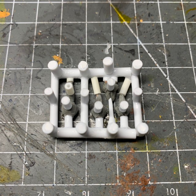
2. Next you need to make a ‘sprue’ for your sculpted muzzle flares. The sprue is the frame that will hold the components during the casting processes. Over the next couple of steps we will be making a rubber mould that makes a negative copy of the sprue, and then filling that rubber mould with casting resin.
Cut your sculpted muzzle flares from the bolters you were using as reference, and then construct a frame as shown in the images below. The size of the frame will be limited by the size of the container you are using for casting (see step 3). The sprue frame will form the channels through which the resin will flow when you inject it into the mould, so you don’t want any ‘dead ends’, otherwise you’ll get miscasts with air bubbles. As you can see below, every flare is connected to the frame at both ends to avoid ‘dead ends’. You may notice I have a larger muzzle flare and a double-flare on the sprue – these are for upcoming projects.

You will also need to add ‘legs’ to your sprue. These keep the bottom of the objects you are casting from touching the floor of the container (if they are touching, the rubber mould won’t enclose them properly). These legs will also form the injection channels through which you will add resin to the finished mould, and will also allow trapped air to escape; although this is the bottom of your sprue, it will end up as the top of your rubber mould. As you can see I have placed legs at regular intervals on the frame, and at the top point of any raised areas on the flares, as this is where air could potentially collect during casting. Try and ensure the legs are even so the mould sits flat in the container (see step 3).
Although it doesn’t matter in this case, it’s worth noting that if you’re casting something that has more detail on one side that the other, such as a head or helmet, the detailed side should be facing outwards on the opposite side to the legs. That side will be the bottom of your mould, and has the lowest potential for air bubble miscasts, preserving the details.
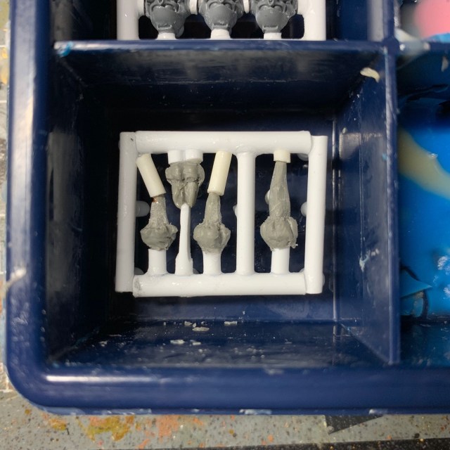
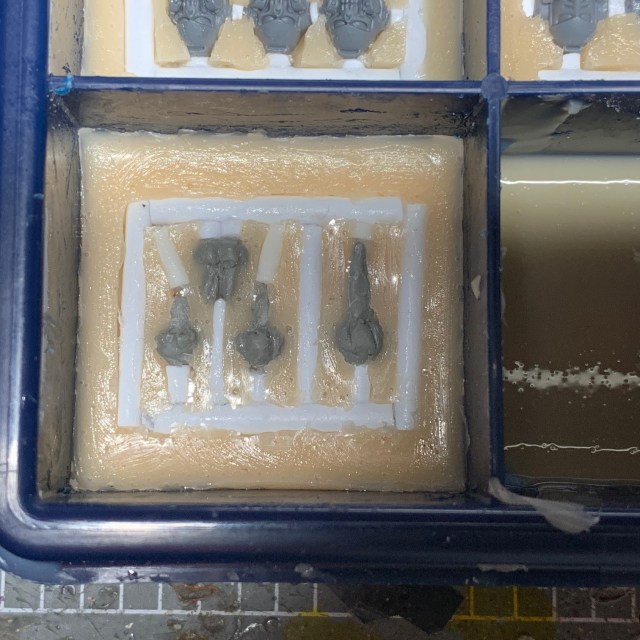
3. Now you need to decide on a container. You want something slightly larger than the sprue, but not much larger as you’ll end up wasting rubber. I use plastic component boxes that are often used for holding different sizes of screw, for example. Coat the inside of the container with Vaseline or similar petroleum jelly. You can buy special mould release agent, but I find Vaseline is cheaper and works just as well. Once you have done that, put a tiny drop of superglue on the bottom of the legs, then press the sprue into the bottom of the container. Wait for the superglue to set, and then to proceed to step 4.
4. Now you need to pour the first half of the rubber mould. If you’re not familiar with mould pouring and casting, then remember you can read my Resin Casting Tutorial. My preferred brand of rubber, I recommend TOMPS Value silicone rubber.
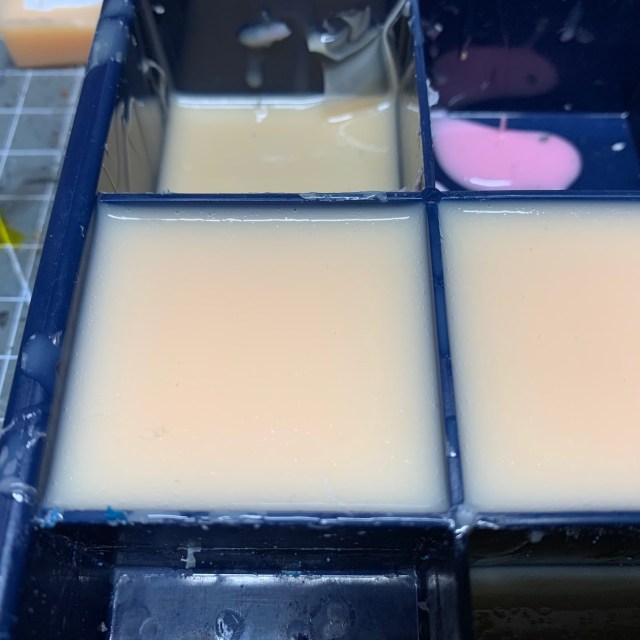
Pour the rubber until it is level with the mid-point of the sprue. This will form the top half of your mould. Once the rubber has set (check the packaging if you are unsure of the cure time), coat the top of the rubber with more Vaseline. This is important as it will help you to separate the two halves of the mould later on. I find you don’t need to put Vaseline on the sprue itself, just the rubber.
5. You can now pour the next half of the mould. This will form the bottom half of your mould. Again, wait for the rubber to set before proceeding to the next step.
6. Once it has set, you can remove the rubber from the container. I find a tool that is thin and flat is particularly useful here, something like a small steel ruler. Prize the mould out of the container, and then gently pull the two halves apart. If you’ve used plenty of Vaseline between the two layers this should be fairly easy to do by hand. If there are any bits that are stuck together you can use a scalpel or fine craft knife to tease them apart.
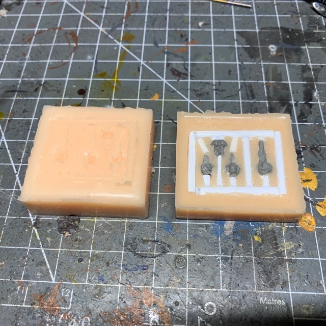
Now you need to remove the sprue from the top half of the mould. Make sure you get all the legs out too, as these can sometimes snap off! I tend to archive the sprues for future use, just in case I ever need to re-make the mould. Homemade moulds like this will generally be good for somewhere between 10-20 casts before bit of rubber wear off and they start to lose detail. So depending on what you’re casting, you may wish to remake them again at a later date.
7. If you turn over the top of the mould, you should see holes where the legs of the sprue were glued to the bottom of the container. If any of the holes have not formed properly – for example, certain individual legs were too short and did not reach the bottom of the container – then you can cut the holes with a scalpel. Remember, you need these holes for allowing air to escape and for injecting the resin. If you’re having trouble seeing where the holes should be, hold that half of the mould up to a bright light and you should be able to see them.
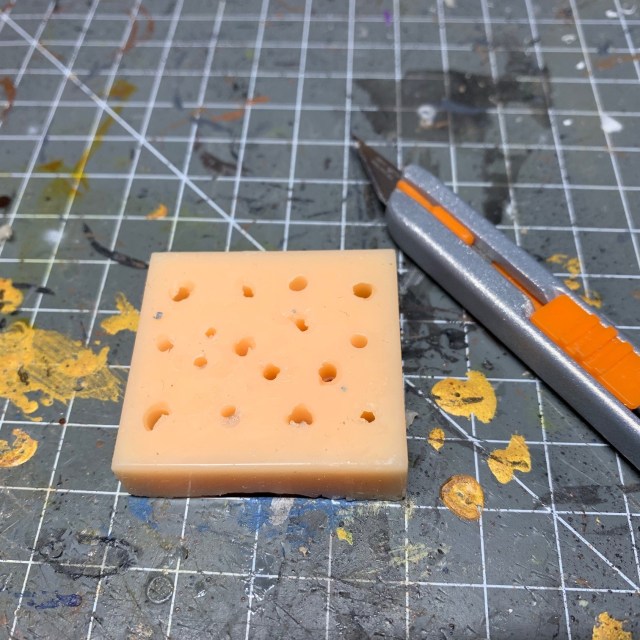
8. To hold my moulds together and keep them level, I tend to cut out a base of thin plastic card and use elastic bands to hold the two halves firmly together, as seen in the image below. Just make sure the bands are squeezing too tight, as you don’t want to deform the mould.
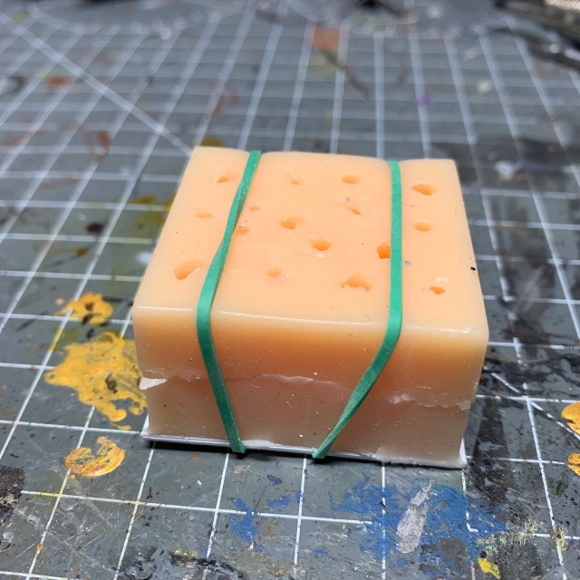
Now mix and inject the resin into the holes in the top of the mould. I like to use TOMPS Polyurethane Fast Cast Resin (the exact polyurethane resins TOMPS stocks vary over time – currently I’d recommend the Axson F190). I tend to use 5ml disposable plastic syringes for the injection process. These are readily available online from retailers such as Amazon. I find it best to inject in several different different holes to ensure that the resin fills all parts of the sprue. Just be careful when withdrawing the syringe that you don’t accidentally pull apart the two halves of the mould. Keep going until there is resin coming out of all the holes. At that point the mould is full.
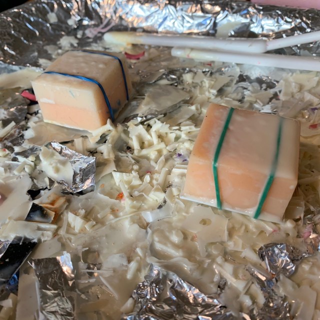
Resin casting is messy and smelly. Never cast in an enclosed space, or if you do, make sure you leave the space immediately after injecting all the resin to allow the fumes time to disperse. I like to use a foil covered plastic tray to hold my moulds. This helps to catch any excess resin run-off that might otherwise damage tables or workbenches.
Wait for the resin to set (consult the packaging for the cure time) and then proceed to step 9.
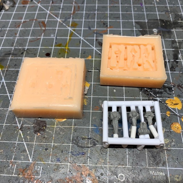
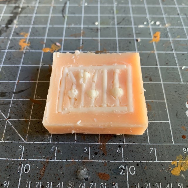
9. Remove the elastic bands and separate the two halves of the mould. You should see your cast sprue, as shown in the image below. Now carefully remove the cast from the mould. If it does not come out smoothly, you may need to strategically snip the resin sprue frame with clippers. If you need to cast more muzzle flares, clean any leftover resin out of the mould with a brush or tweezers, and then return to step 8. Otherwise, proceed to step 10.
10. Now it’s on to the miniature itself, starting with the base. First, complete step 1 – 5 of my LED eye lens tutorial to assemble the base and battery holder, then proceed to step 11 of this tutorial.
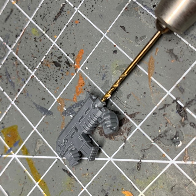
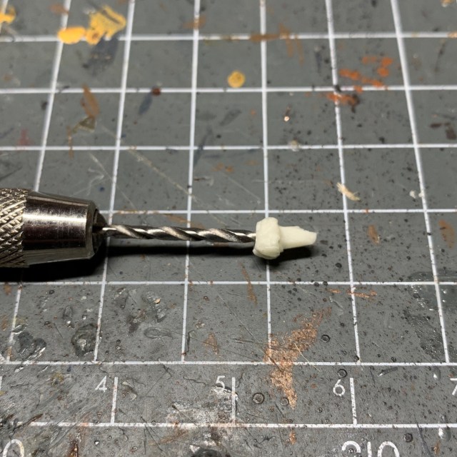
11. Now you need to drill out the barrel of the gun. You’ll need a very fine drill bit for this. The image below shows a 1mm drill being used in the bolt carbine. The hole needs to be drilled most of the way through the gun. This is to allow the wires of the LED to pass through the gun and into the arm of the model, and then ultimately into the torso and the base. I found the best way to drill the gun was to drill a hole through the barrel and keep going until you are level with the rear hand grip, then cut off the hand and drill a hole up into the the gun until it meets with the first hole. Make sure you save the hand as you’ll need it again later.
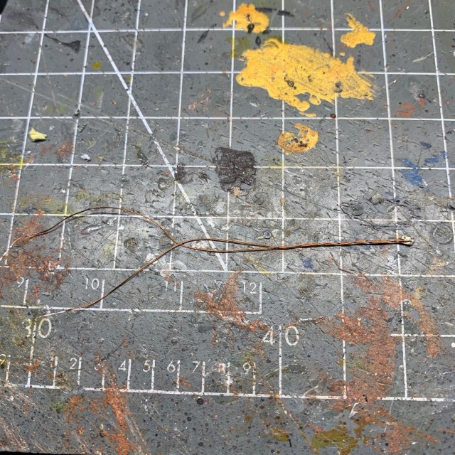
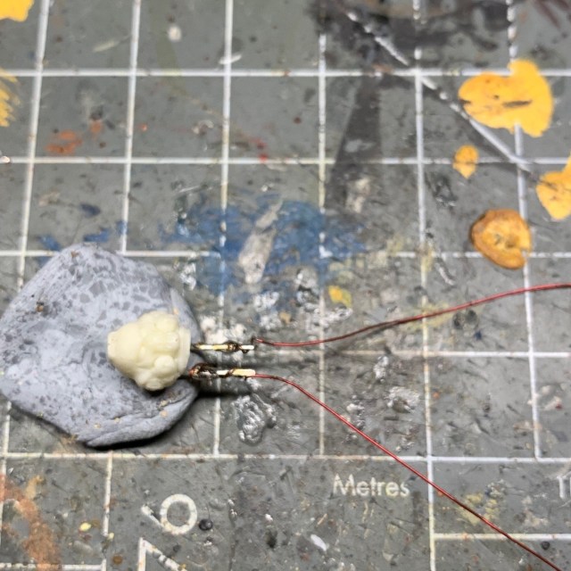
12. Now you need to prepare the LED. For this model I used a Yellow/Amber 0805 Chip LED (3V) from the website Small Scale Lights. As an aside, I really like this supplier – they have a good range of products and excellent customer service. You will need to prepare the LED so it looks like the one in the image below. This is fairly simple – just unsolder the red and black insulated connecting wires, leaving yourself with only the enamel coated wires shown below. This is done because the enamel wires are easier to work with as they are significantly thinner than the insulated wires. Just make sure you note which wire was positive (red) and which was negative (black)!
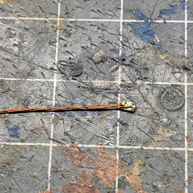
Below is a close-up of the LED chip itself, for reference. You do not need to do anything to this end of the wire.
Feed the wires through the hole you drilled in the gun during step 11. You may need a pair of fine tweezers to help with this.
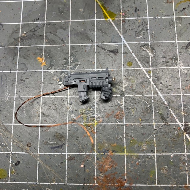
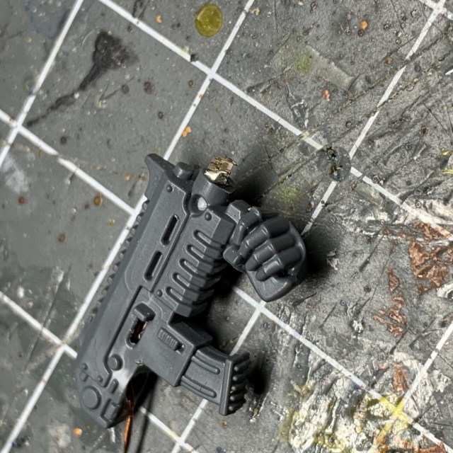
Pull through the wire slack until you the chip LED is sitting flush with the barrel of the gun, as shown below.
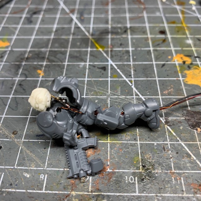
13. Now drill a hole through the arm and torso of the model and feed the wire through, as shown below.
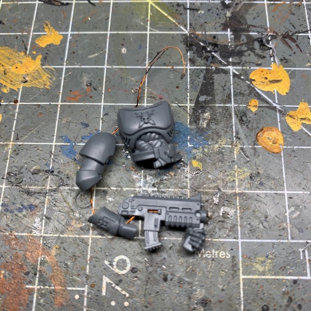
14. Now insert your other LED into the resin helmet of your model. This is covered in detail in steps 11 – 14 of my LED Eye Lens Tutorial, so I won’t go over it again here. For this model I used one of the TruOpto OSHR7331A-KL 1.8mm Red LEDs that I use with all my Crimson Fists. Once you have inserted the LED into the helmet, solder wires to the two LED legs. Again, don’t forget to note the polarity of the legs.
Designer’s Notes: Non-LED Heads
If you don’t want an LED in the head – for example, the miniature has a bare head – then you can simply skip this step, and skip step 15 below that deals with adding a resistor to the base.
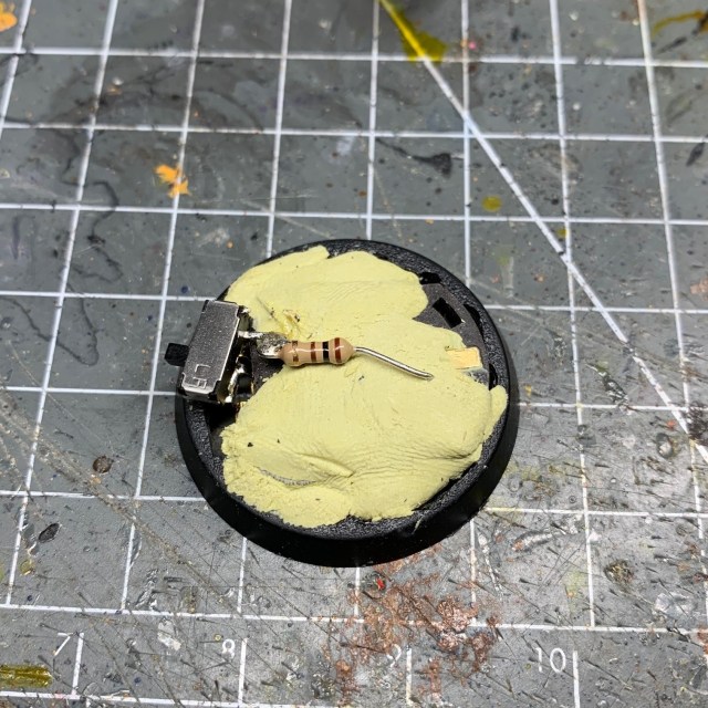
15. If you’re following this tutorial to the letter and using two different types or colours of LED then one of them will probably need a resistor in the circuit to balance the current draw – different LEDs will have different current draws. If you’re not sure how to determine what type of resistor you need then that is covered in my designing LED circuits tutorial. If you’re using the red TruOpto 1.8mm LED and the Yellow 0805 chip LED then the best resistor to use – connected in series with the red LED – is a 100Ω resistor (any brand will do).
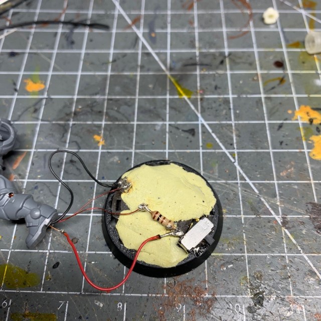
If you look at the image below you can see I’ve simply soldered the resistor to one of the terminals of the switch. The yellow material is Milliput modelling putty that I have used to hold the battery holder inside the hollow base. You can use whatever modelling putty you want for this purpose; Green Stuff is also fine, for example.
16. Now drill a hole through the legs and pass the wire down through the torso and out of the bottom of the legs, pulling any slack through. If you make any extra holes in the legs then don’t worry, these can be filled with modelling putty later.
It can be useful to mark which wire is which before you feed them through – if you haven’t already – so you know which wires are connected to the positive side of the battery, which are connected to the negative side, and which is the one connected to the resistor (if you are using one). You can mark the ends of the insulation with a tiny dot of paint, or similar, as a reminder.
17. The next stage is to solder the wires onto the battery holder. Connect the negative (black) side of both LEDs to the negative terminal (seen on the left-hand side of the image below). I normally solder my switch onto the positive battery terminal, which means the positive (red) sides of the LEDs should be connected to the unused terminal of the switch. If you are using the resistor in series with one of the LEDs – the red TruOpto 1.8mm LED in this case – then the positive wire from that LED should instead be soldered onto the end of the resistor rather than directly onto the switch (seen on the right-hand side of the image below).
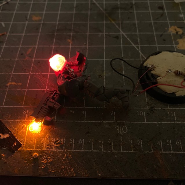
Once you have made the connections, test the circuit by turning on the switch! If the LEDs illuminate, excellent work, you may now proceed to step 18. If it doesn’t work, this is the point to back-track and start fault find. Check all connections that you have soldered so far. A digital multi-meter with probes is handy for this.
18. Now we need to drill out one of the cast resin muzzle flares. Remove the one you want to use from the cast sprue, if you haven’t already, and clean off any excess resin. The muzzle flare needs to be mostly hollow to allow the light to propagate and be visible from all sides. I recommend drilling a wide hole in the ‘base’ of the muzzle flare that is wide enough to accommodate the chip LED, then drilling a narrower hole further into the rest of the resin. Be very careful at this stage! If you accidentally break the muzzle flare or drill through the surface then you’ll have to throw it away, grab another one from the sprue and start drilling again. Only dry fit the muzzle flare at this stage to test it, don’t glue it into position.
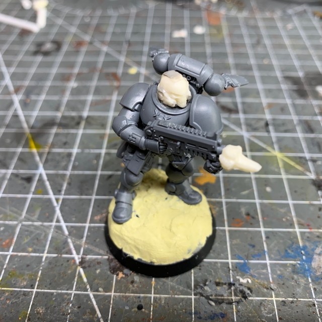
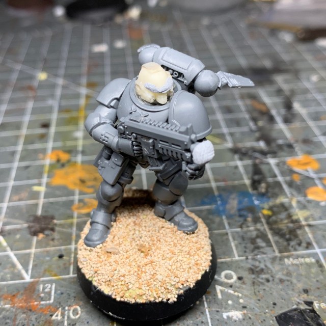
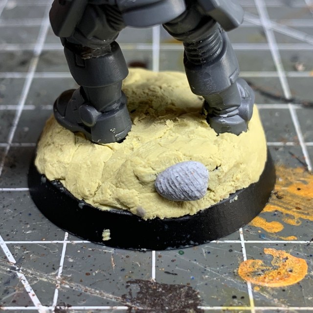
19. Now you need to glue the model together, if you haven’t already. Don’t forget to glue the hand back onto the grip of the gun if you cut that off earlier. If the hand is not in two parts as it was in on the Reivers, you may need to drill a hole in it to accommodate the wires. Now attach the finished model to the base. I find the best way to do this is to put two small balls of modelling putty under the model’s feet, press it into the putty so it’s standing up, then wait for the putty to cure and harden before proceeding further. This helps to make sure the model is attached to the base in the correct pose and position before going on to hide the rest of the wires and connections. Any slack in the connecting wire should be curled up under the model on the base.
Test the circuit again at this stage, just to make sure you haven’t accidentally damaged any of the connections.
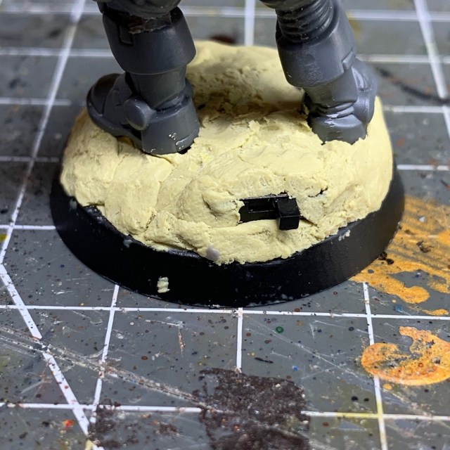
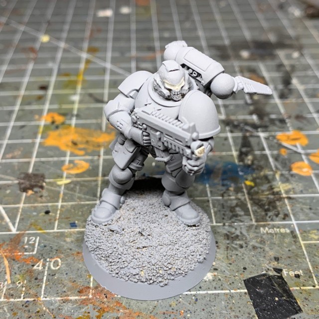
20. Now cover the rest of base in putty to hide all the wires and connections. Just make sure you leave the moving parts of the switch accessible, as shown in the second image below. This is also your opportunity to fill in any holes you may have accidentally drilled, e.g. in the legs.
21. Now you need to prepare the model for adding texture to the base and the undercoating process. Remove the resin muzzle flare (you haven’t glued this yet, right?) and use blu-tack (or similar) to cover the chip LED, the eye lenses and the switch. This is extremely important, otherwise you could ruin all your hard work so far!
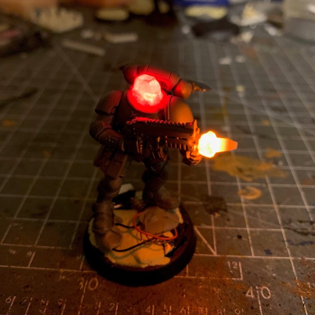
22. Once the base text and undercoat spray have been applied, carefully remove the blu-tack from the eyes, chip LED and switch.
23. Now apply paint, avoiding the eye lenses and the muzzle flare LED chip. Once you have finished painting, put the resin muzzle flare on the end of the gun and hold it in place with a tiny drop of PVA glue (wood glue). Try not to get any glue on the LED chip itself. If you find the light is leaking through in any area it shouldn’t, especially from the resin helmet, then an extra coat of paint will normally sort that out. And that’s it! I hope this tutorial was helpful!

Designer’s Notes: Energy Weapon Muzzle Flares
All the techniques described above can equally be used to make muzzle flares for energy weapons. You’ll simply need to sculpt a different shape of muzzle flare and cast a new sprue. The example shown below is a ‘volkite charger’ heat ray from the Horus Heresy setting. The concentric rings were designed to match the artwork for the weapon.

Black, No Sugar. Thank you!
![]()
All my tutorials are entirely free; the only payment I really need is seeing everyone’s awesome LED armies on the battlefield! Having said that, if you found these tutorials useful and you’d like to buy me a coffee to say thank you (or help keep my supplied with LEDs and website fees so I can post even more tutorials) then please click the button above. Thanks very much in advance!
