
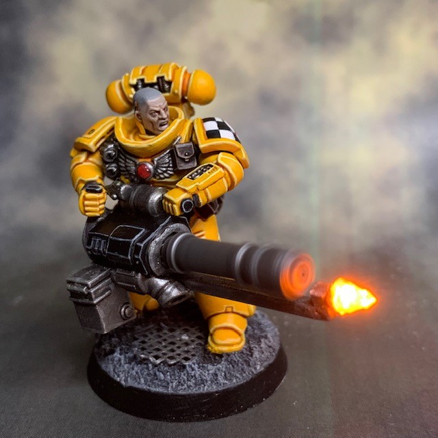


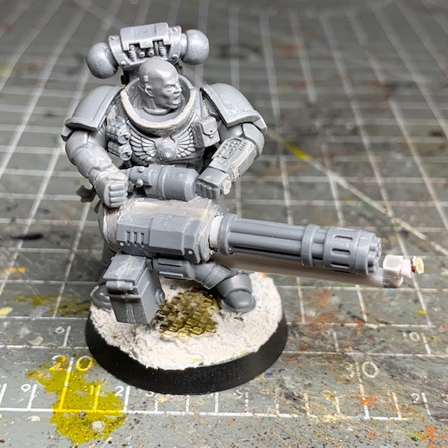
This is my tutorial for placing miniature motors and LEDs inside Space Marine assault cannons. The photos in this guide show the technique applied to an assault cannon on an infantry model, but it can equally be applied to any other model with a multi-barrelled rotary cannon, such as the Dreadnought shown in the image above.
I strongly recommend reading through the entire tutorial before starting work, just to make sure you have the necessary skills and tools required and that you’re not going to run into an unexpected barrier halfway through. If you need to know where to buy tools and consumables for this type of project, you can buy them here.
I have a separate tutorial about designing LED circuits and basic LED soldering. This tutorial assumes you’ve either read these, or are familiar with the techniques discussed.
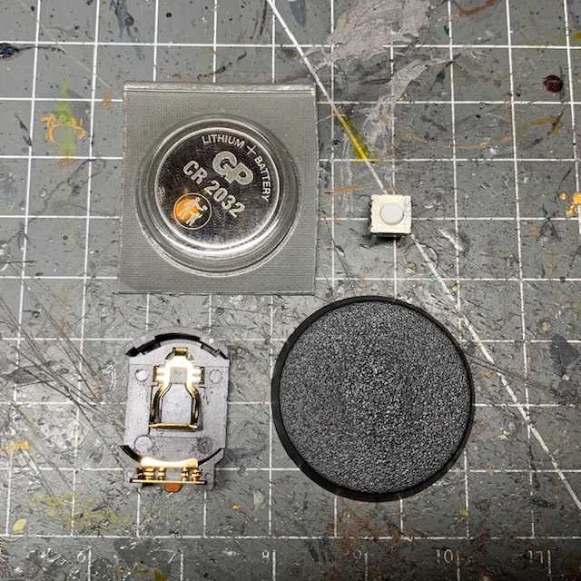
1. Start by selecting the type of battery you want to use. I prefer CR2032 coin cells. These are the lithium memory back-up batteries you find in PC motherboards, among other things. I like these because they last a long time, can power the brighter 3V LEDs and, most importantly, because they have a low profile that will fit inside a standard base for a 28mm scale model.
You’ll also need to select a suitable battery holder. Many types are available but it’s important to pick one that will fit inside your base. Personally I like the catchy-named Multicomp Battery Holder SMT, 20mm, CH7410-2032LF (available from Farnell here), since it fits comfortably inside a GW 32mm base (the current standard Space Marine base) without any trimming. This is just personal preference, as long as your battery holder fits inside your base then you should feel free to use any brand.
For this project you will also need a switch. I selected a ‘push to make’ miniature button switch. This is a type of switch that will activate the circuit only while the button is pressed. I selected the B3W-1020 (available from Farnell here) as it was the best combination of small, cheap and available. But any similarly sized 6mm x 6mm tactile ‘push to make’ switch will do. I’ve used this type of switch rather than the normal slide switch to allow for quick “bursts of fire” while the miniature is on the table top without the need to pick it up and move a slide switch. The assault cannon will only “fire” when I push the button!
2. Now we have our components we need to get the battery holder in the base, which means cutting out the middle section of the base. I find the best thing to do is to drill a number of small circles in the top of the base around the edge. Then cut out the top of your base by using a craft knife or similar to cut between the holes. I find this is easier than just cutting it with a knife from scratch. Just make sure you leave the rim intact, as shown below.
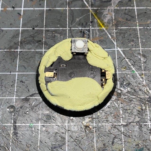
Insert the battery holder into the base. Make sure the actual battery is inserted into the holder for this step. Position the battery holder so that the side that you insert the battery is face down (this will allow you to change it without disassembling the model) and so that the bottom of the battery holder is flush with the lower edge of the base. This should mean that when you put the base on a flat surface, it is level.
Please note that if you do not have the battery in at this step, you may later find that when you insert the battery, the battery and holder are not flush with the bottom of the base and your model will not be level! This is especially true of battery holders with clips.

3. Once the battery holder and switch are inside the base, you need to secure them in place.
Do not glue the switch to the battery holder! These switches are not sealed against liquids and there’s a high chance the superglue will penetrate the switch and insulate the contacts when it dries, making the switch non-functional!
To secure the battery holder and switch in place, simply fill the gaps around the edge of the base with modelling putty – such as Milliput or Green Stuff – and allow it to dry. Note that if you are using the B3W-1020 switch then you will only need two of the four legs (on the same side), so it’s worth bending them upwards at this point to ensure they are accessible. The other two legs will not be used and can be clipped off the switch if you want to save space.
Be careful not to cover the two metal battery terminals with putty as you will need to access those later!
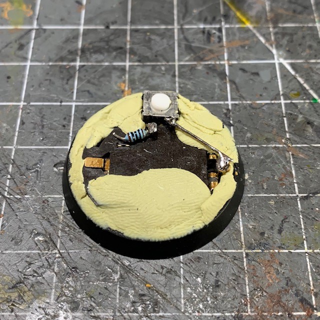
4. Next add wire to connect one terminal of the switch to the positive terminal of the battery holder, as shown on the right of the image below. Any narrow gauge wire will do to make this connection (if you need wire, check here).
Be careful to never short the battery by directly connecting the two terminals. Lithium-based coin cells can get very hot and potentially explode or start fires if the terminals are connected for extended periods.
Next connect a 100 Ohm resistor to the other terminal of the switch, as shown on the right of the image below. Do not connect the other end of the resistor yet, we will come back to this later when it will be used to ‘balance’ the current between our motor and LED.
5. Now it’s time to prepare the assault cannon. I used the pintle-mounted assault cannon from the Space Marine Primaris Repulsor kit. Carefully cut the barrel from the assault cannon, as shown below. Make sure the cut is straight down otherwise the barrels may appear off-centre when they spin later.

6. Glue the barrels together, then glue a 4mm diameter plastic rod to the ‘base’ of the barrels, i.e. the section that will go into the body of the assault cannon. This section of rod only needs to be a few millimetres high. I’d recommend starting at around 2mm and you can trim it down later if you need to. Now drill a small hole in the middle of the plastic rod that is the same diameter of the ‘shaft’ of the motor (the bit that spins). Check the shaft diameter in the specifications of the motor you ordered (I talk about the motor in the next step). You’ll probably find it is somewhere between 0.6mm – 0.8mm, which may requires some very small drill bits (if you need miniature drill bits you can find some here)! Make sure this hole is central, otherwise the barrels will spin off-centre. You may find it useful to draw a cross in pencil on the end of the rod to help you position the drill correctly.

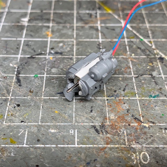
7. You will now need to fit your miniature motor into the main body of your assault cannon. You will need a 3V or 3.7V miniature motor. A wide variety are available online, including these here. Any 3V – 3.7V miniature motor that is between 4mm – 6mm wide and 10mm – 12mm long will be suitable. Hollow out the body of assault cannon so that your motor fits neatly in the middle. This can be achieved either with a craft knife and needle files or a small Dremel. This is probably the most time consuming part of this build! Don’t worry if you make holes in the sides as this can be repaired with putty later.

8. Test fit the motor with the shaft emerging from the front where the barrels will sit and the wires protruding from the back. If you find that the two halves don’t fit back together neatly then you may need to add plastic card spacer as I’ve done here. This was a section of the 2mm square rod that we’re going to need to use for the next step. Again don’t worry about gaps, they’re inevitable and can be filled later.
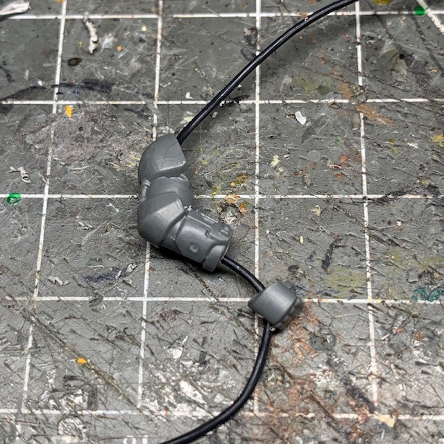
9. The next step is to build the lower support arm of the assault cannon. This will give it that classic assault cannon look, while also incorporating and hiding the LED used for the muzzle flare. The support arm was built out of hollow square 2mm x 2mm plastic rod to the pattern shown below. The dimensions required will vary depending on your exact motor and which assault cannon model you are using, but if you are following this tutorial to the letter you will need to make it about 35mm long.
The support arm is made from three sections; the ~35mm horizontal length, the much shorter ~5mm vertical length, and the short section of 2mm diameter rod that forms the muzzle itself. You may find it easiest to insert the LED wires through the separate parts of the support arm before gluing them together. The LED used is a single ‘0805 Chip LED’ 3V yellow LED available from Small Scale Lights. If your LED is supplied with thicker wire connections for soldering on the end of the thin wires then you may find it useful to remove these before trying to feed the thin wires through the square rod. These thicker wires can be cut off or desoldered, whichever you find easier.

10. The next step is to consider how you will get the wires from the motor and the LED to the battery in the base. As with my other LED miniature tutorials, my preferred approach is to run the wires through an arm, into the body and down through a leg. I chose to drill through the right arm as this is going to be nearest to where all the wires gathered at the rear of the assault cannon.
Designer’s Notes: Which arms?
If you want to use the same Space Marine components that I used, you will need the Space Marine Primaris Intercessor boxed set, torso ‘1C’, and arms 53 and 63. These arms were chosen as they most suited the intended pose.
Because the arm is bent it’s easiest to remove the hand, drill two holes from opposite ends and meet in the middle. The hand can be drilled separately. You can make an additional cut in the arm just above the elbow armour if you’re having difficulty making the two holes meet. The arm can always be re-glued later. I use a 1mm drill bit for accurate drilling, and then widen the hole with a 2mm drill bit to make sure it can accommodate all the wires.
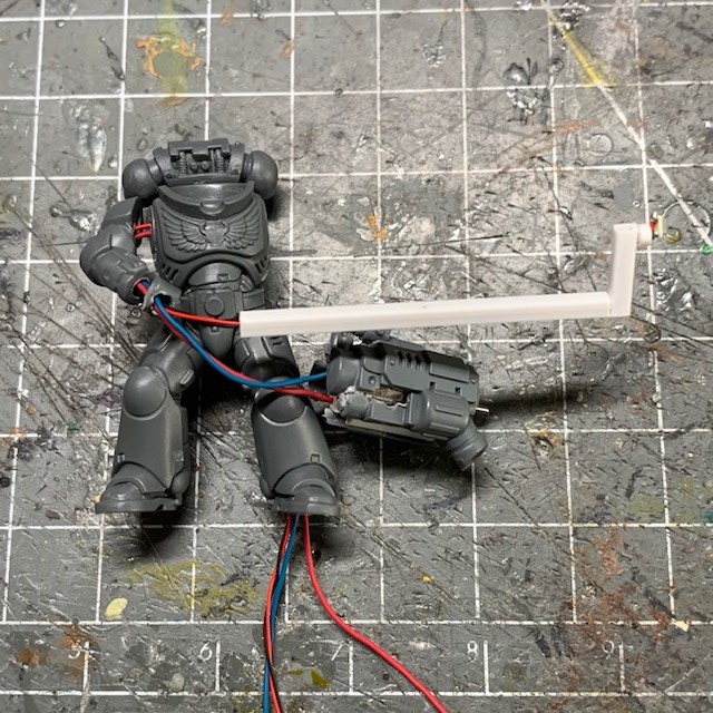
11. Now drill through the torso and legs so your wires will have a path to the battery in the base, as shown below. It’s always easiest to drill whichever leg is in the straightest pose. Don’t worry if your drilling accidently breaks the surface at any point, any gaps or damage can be repaired with putty later.

12. Feed both sets of wire from the motor and the LED through the arm, torso and leg. Pull the slack through so that all the spare wire is underneath the model’s feet, and then glue the torso and legs together.
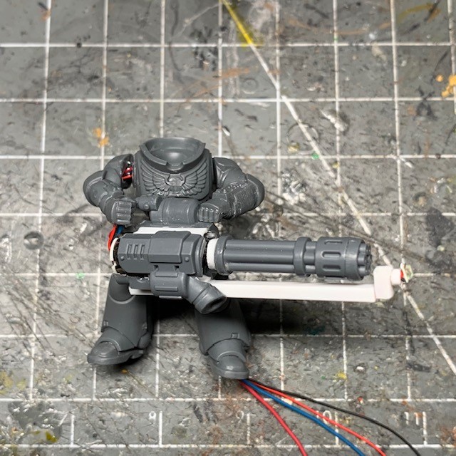
13. Arrange the model in the pose that you want and glue the arms into position. Now attach the barrels to the assault cannon by inserting the shaft into the hole you drilled in the rod on the base of the barrels. If you think the barrels protrude too much, simply file a bit off the rod or drill the hole a little deeper until you get a fit that looks good. Once you have done that you can glue the support arm into place, as shown below.
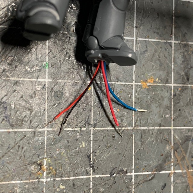
14. Cut the majority of the slack from the wires, leaving just enough to reach the battery connections once the model is posed on the base, as shown below. Strip the ends of the wires to expose the metal so they are ready for soldering. Wire can be stripped with either a dedicated wire stripping tool or a sharp craft knife.
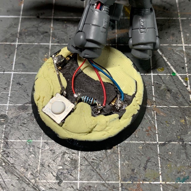
15. Solder the negative (black/blue) wires to the negative (-) battery terminal. Solder the positive (red) wire of the LED to the terminal of the switch. This is the left-hand red connection shown in the picture below. Solder the positive (red) wire of the motor to the other side of the resistor that was left unconnected earlier. This means that the motor is in series with the 100 Ohm resistor and the LED is not. If you need to know which wire is which, the LED wires will likely be thinner than the motor wires.
16. Glue the model to the base, being careful not to get any glue in the switch or battery holder. After the glue has dried and the model is firmly attached to the base, you can assemble the rest of the model. This is also a good opportunity to repair any unintentional damage with modelling putty (e.g. the hole in the back of the leg shown below). You will also want to cover the rest of the components in the base with putty to allow you to texture and paint the base later – just don’t cover the button on the switch!

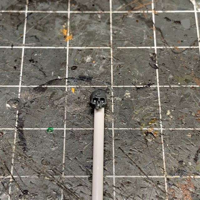
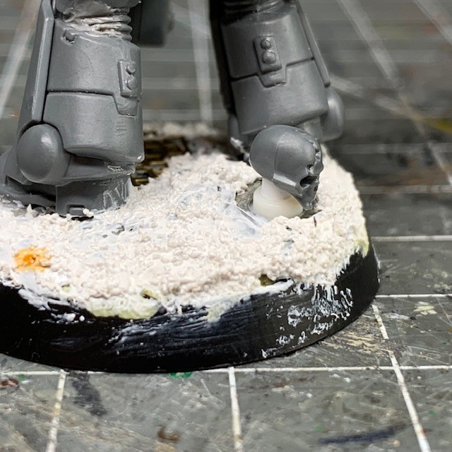
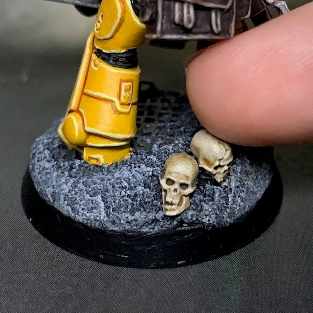
17. Now you will need some method of concealing the button on the base. I like to use small plastic skulls. No-one bats an eyelid at a skull on the battlefields of the 41st millennium, so the switch will pass entirely unnoticed. Start by attaching a plastic skull to a 2mm plastic rod.
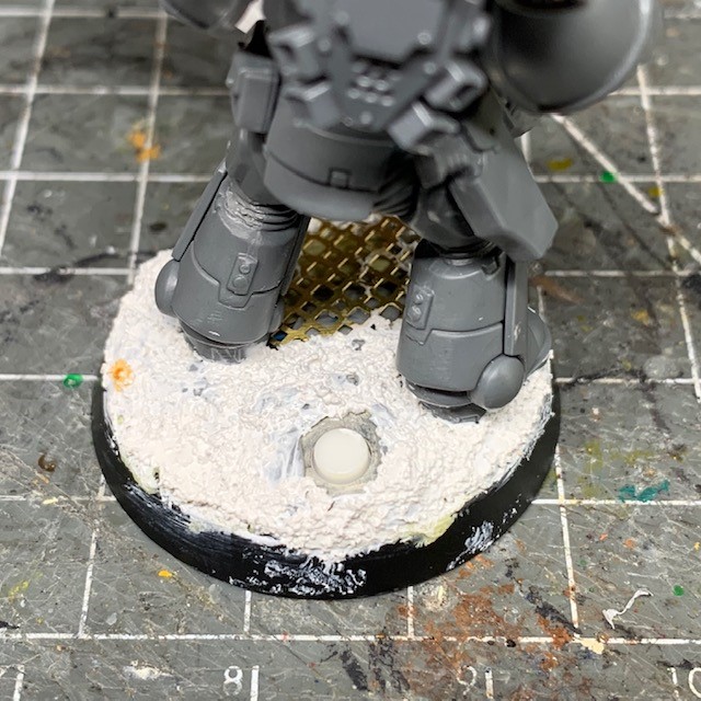
18. Cover the base with your chosen texture medium, leaving the button exposed. Now cut the rod from the previous step down to a few millimetres in length. Use a very small amount of glue to secure it in place on top of the switch button, as shown below. Do not get glue around the edges of the button or it may stop working! Now build up the texture around the button and skull until you are satisfied with how they are hidden.
19. Fill any remaining gaps with putty and add any details and accessories you want to the model.
20. Your model is now ready for priming. Make sure you cover the LED, the gap where the barrels join the body of the assault cannon and any remaining gaps around the switch with blue tack or something similar to protect them from the undercoat spray!

21. Remove the blue tack and begin painting. Once you have painted the support arm of the assault cannon you can start building up the muzzle flare. Apply Water Splash Effect Gel, available from Green Stuff World, directly to the LED to build up a “muzzle flare” shape. Start building the basic shape as shown below, then allow that to dry before applying more gel, building up the muzzle flare shape in layers. The gel will initially be a milky white when first applied, but will become transparent when it dries. Drying can take up to 24 hours, depending on how thickly you’ve applied it. When deciding on the shape of your muzzle flare, Google is an excellent source of reference images.
If you’ve followed my other LED muzzle flare tutorial you may recall that I normally use resin casting to achieve this effect. The reason I’m going in a different direction with this one is so that the flare “disappears” when the cannon is not firing. This helps to add to the illusion of time passing and the model being active, rather than having a resin flare that is always visible. If you’d like a more detailed discussion of design philosophy and “the passage of time” in LED miniatures, check out point 4 in this article.

22. Continue to build up multiple layers of the gel until you are satisfied with the muzzle flare shape.

23. Finish painting the model, and then that’s it, you’re done!
As well as power armoured Space Marines with assault cannons and rotor cannons, this technique can also be applied to Space Marine Terminators.

All these tutorials are entirely free; the only payment I really need is seeing everyone’s awesome LED armies on the battlefield! Having said that, if you found these tutorials useful and you’d like to buy me a coffee to say thank you (or help keep me supplied with LEDs and website fees so I can post even more tutorials) then please click the button above. Thanks very much in advance!
