


This is my tutorial for LED energy shield special effects. The idea behind this effect is to give the impression of an invisible energy bubble around a model that is becoming “active” and visible as it is hit by an incoming projectile. The photos show this technique applied to the ion shield of an Adeptus Titanicus scale Knight Lancer, but it can equally be applied to any other type of energy shield, such as a Space Marine storm shield or T’au Empire shield generator.
I strongly recommend reading through the entire tutorial before starting work, just to make sure you have the necessary skills and tools required and that you’re not going to run into an unexpected barrier halfway through. If you need to know where to buy tools and consumables for this type of project, I have recommendations here.
I have separate tutorials about designing LED circuits, basic LED soldering, resin casting and LED eye lenses. This tutorial assumes you’ve either read these, or are familiar with the techniques discussed, especially the eye lens tutorial, which is a starting point this tutorial builds from. Resin casting skills are essential (this tutorial references my LED muzzle flare tutorial where two-part epoxy resin casting is explained in detail) as the explosion impact on the shield effect relies on the availability of “explosions” cast in two-part epoxy resin, and the shield itself is cast in UV resin.
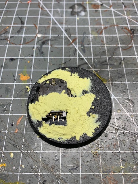
1. First you will need to prepare the base by cutting out a space for the battery holder and switch, then filling in any gaps with modelling putty, as seen in the picture below. If you haven’t seen any of my other tutorials and aren’t familiar with the battery process then detailed instructions can be found in steps 1 – 5 of my LED eye lens tutorial.
2. For this tutorial I’m going to assume that you’re using exactly the same LEDs as me, namely a 3V 0805 yellow chip LED for lighting the explosion and a 3V Nano SMD red chip LED for lighting the eyes of the model, both of which are available from Small Scale Lights. Depending on your tastes you may want to leave out the eye LED or substitute your own LEDs, but the tutorial will only refer specifically to the LEDs that I used.
At this point you’ll want to add a 200 ohm resistor to the free terminal on the switch. This will eventually go in series with the red LED (note: in the image below I’ve used two 100 ohm resistors in series as I didn’t have a 200 ohm resistor to hand). If you’re not using an LED for the model’s eyes then skip straight to step 4. Otherwise proceed to step 3.

3. If you’re having LED eyes then you now need to select your head. It’s important to know which head you will be using at this stage as you will need to recast it in epoxy resin.
If you are following this tutorial for a Adeptus Titanicus knight then I found it was easier to cut the front off the head so there was less to recast, and save the plastic “neck” for later use. Put it somewhere safe, because you’ll need it again in step 15.

4. Next you’ll need to sculpt some “explosions” from modelling putty, as shown on the left of the image below. Google images can be a handy reference tool for this. I went for a sort of “blossoming flower” shape, but just go with whatever shape you think looks cool.
Once the putty of your explosions had hardened, add them to a sprue for casting in two-part epoxy resin, along with the front of the head you selected in the previous step. If this is your first attempt at casting then you can find detailed instructions on sprue creation in my Resin Casting tutorial and steps 1-9 of my LED Muzzle Flare tutorial.
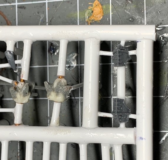
5. Once you have created the silicon rubber mould and cast your heads in two-part epoxy resin then you will be left with resin copies as shown below. Links to my recommended two-part epoxy resin can be found in my Resin Casting tutorial.

6. Now it’s time to start drilling some holes in your model to accommodate the wires. These will run up from the battery holder in the base, through the leg and torso and into the shield arm and head. If you’re using the chip and nano LEDs from Small Scale Lights that I mentioned earlier then they will be supplied with their own wires already attached. These wires are very thin, so I used a hand-held pin vice drill with a 2mm drill bit for all the drilling, although you need to be quite careful on some of the thin components such as the Knight arms.
Firstly, select which leg you wish the wires to run through. It’s advisable to use the straightest leg for drilling convenience. Drill a hole in the centre of the corresponding foot for that leg.

7. Now it’s time to drill through the leg. I found it most convenient to cut the leg into smaller sections to allow easier drilling. If you cut at every bend then you will only ever have to try and drill in a straight line.

8. Once you have drilled all the holes just run a spare length of wire through to test that all the holes are clear and that they line up, as shown below. You can remove this wire again once you are satisfied.

9. Now drill a hole through the pelvis of the model. Helpfully this component is hollow on a Knight Lancer so you can simply drill a hole through the hip joint and the waist joint. They will then connect in the cavity in the middle of the component.

10. Fit the two halves of the torso together and then drill a hole through the bottom of the torso at the waist joint.

11. Drill a hole in the neck joint of the panel that covers the front of the torso. This is to allow the wires to pass through to the head later.

12. Decide on which arm of the model you want to mount the shield. Now drill a hole through the corresponding shoulder joint on the torso and the top part of the arm.

13. Now you need to drill through the lower part of the arm. I found it easiest to cut the shield hand from the lower arm and to drill each section individually. When drilling through the hand I drilled in from the wrist until I reached the centre of the hand, and then drilled in from the point where the shield attaches. That way the holes should connect in the middle of the hand.

14. Drill a hole through the centre of the shield. This hole needs to be comfortably wide enough to pass the yellow chip LED through for ease of assembly, not just the wires. You may find a 3mm drill bit is best for this.

15. Drill hole through the plastic “neck” (that you retained from step 3) for the head LED wires to pass through.

16. Now you need to drill a hole in the back of the cast resin head to accommodate the red nano LED. This hole should line-up with the one you drilled through the neck in the previous step and should be as central as possible to the head. Drill slowly and carefully – if you drill all the way through then the drill bit will emerge from the middle of the “face” and you’ll have to cast a replacement! Insert the nano LED and power it on (using a coin cell held between the two ends of the wires with your fingers) to check that it’s positioned centrally, that the hole is deep enough so that the eyes look bright, and that you’re illuminating both eyes equally. If this is your first time trying this technique you may find this takes a bit of trial and error. When you are happy with the hole you’ve drilled and the position of the LED, put a tiny blob of PVA glue into the hole to fix the nano LED in position, then wait for it to dry.
Once the PVA has dried, feed the nano LED wires through the plastic neck and then use a small amount of superglue to attach the head to the neck. Don’t be afraid to trim the back of the head or the neck with a modelling knife to make a smooth fit in necessary. Fill any gaps around the join with modelling putty.

17. Now it’s time to insert the LED wires into all the holes that you’ve drilled. Run the wires from the head LED through the hole in the neck joint on the front of the torso, down into the torso and through the hips, down the leg and out through the foot. Do the same with the explosion LED, except you need to run it through the shield arm.
The wiring can be seen in the picture below, with the red nano LED on the top left of the picture (it’s not in the head in this image) and the yellow chip LED on the top right. It’s worth noting that the red nano LED has thin copper coloured wires and the yellow chip LED has thicker red and black wires.
Once you have fed the wires through, you can solder the negative wires from both LEDs to the negative terminal of the battery holder. The positive wire of the yellow chip LED can be soldered directly to the same switch terminal that the resistor(s) are soldered to (the red wire in the image below). Then the positive wire of the red nano LED can be soldered to the free end of the resistor(s). This means that the red nano LED is in series with the resistor(s) and the yellow chip LED is not. This is to help balance the different current draws of the different types of resistor (something I talk about more in my LED circuit design tutorial).

18. This is a good point to switch on the circuit and test that everything is working. If it isn’t then you can troubleshoot now before doing any further assembly. If the LEDs light up and you’re happy with how they look then you’re good to proceed.

19. Now it’s finally time to assemble the model. Glue all the remaining pieces together following the assembly instructions. When gluing two model components connected by wires be careful not to glue the wires in place otherwise you may lose the ability to adjust the slack in the wires – particularly the yellow explosion LED – if the wires can no longer move. Once you have finished assembling the model switch on the LEDs to check they are still working before proceeding.
Leave about 1-2cm of slack on the yellow chip LED emerging from the shield. You’ll need this slack as the curve of the energy shield effect will separate the explosion effect from the centre of the shield.
Any remaining slack in both LED wires can be curled up under the feet of the model and then be concealed under a thin layer of modelling putty and whatever it is you prefer to use to texture your bases.
Once you’ve done all that it’s time to undercoat your model. It’s important that you cover the eyes of the model and the chip LED during undercoat spraying so they don’t get paint on them. The eyes can be covered with a small amount of blu-tack and the chip LED can be covered with one of those small plastic tubes that protect paint brush bristles with a small amount of blu-tack covering the open end. Don’t apply blu-tack directly to the yellow chip LED in case you accidentally damage the soldered connections while removing it later.
You may also notice in the image below that I haven’t glued the top of the carapace onto the Knight. This is so I can adjust the slack of the wire in the shield arm yellow LED if I need to by pulling it through into the torso.

20. While your undercoat is drying it’s time to return to the explosion effect. You need to drill a hole in the resin “explosion” that is large enough to accommodate the yellow chip LED. A 4mm diameter hole is ideal as it allows the LED to fit comfortably inside and for the light to diffuse a bit too. Again you will need to drill carefully and test that you are happy with the depth of the hole, as described for the head in step 16.
Something else that I also like to do is paint resin effects with a glaze so that they still look good even when the LED is off. As long as the glaze isn’t too thick this won’t inhibit the light coming through. To achieve this I apply an orange shade (Citadel Fuegan Orange) and then a thin yellow glaze (Citadel Lamenters Yellow).

21. Next it’s time to make the energy shield surface. You will need a smooth curved surface for this, such as a small plastic ball or a toy egg as shown in the image below. Polystyrene balls won’t work as they are not smooth enough.
What I also found it useful to do was drill a 2mm diameter hole into the egg and insert a 2mm plastic rod. This gives you a fixed reference point as the centre of your shield effect and also acts as a hole which you can pass the yellow chip LED through without the need to drill through the delicate shield.

22. The shield was created using Green Stuff World‘s UV Resin and cured using their UV Torch. Pour very slowly and carefully to avoid air bubbles forming. I’d recommend starting in the middle near the plastic rod and working outwards in a spiral pattern. Don’t worry if you get runaway drips over the edge, you can always trim them off later.
Once you are happy with the size and shape of your shield, give it a 30 second exposure with your UV torch. If the surface still feels tacky after that then leave the resin in direct sunlight for about an hour to finish the curing process.

23. Once you are certain the resin is cured, slowly peel it off the curved surface. I found it best to work around the edges and free all of them first. If you apply too much force the resin will snap as it can be brittle when thin. Once the shield is free of everything except for the plastic rod, I found it best to remove the rod from the ball/egg, clip it flush with the shield and drill it out with a 2mm drill bit. Although it still has to be done carefully this is less likely to result in an accident than pulling on the resin to remove the rod or drilling the resin itself.
Once the resin shield is free you can very carefully trim the edges with a craft knife to remove any drips and get a shape you are pleased with. I think slightly jagged is best as it looks like the shield is reacting to the random shape of the explosion. However you might decide smooth curves are best if representing advanced Aeldari or T’au Empire shield technology.
Don’t worry if step 22 and 23 take a few attempts, it took me about five tries to get something I was happy with!

24. Next I applied blue ink to the shield using an airbrush. This was Green Stuff World‘s Sapphire Blue Candy Ink to give the impression of electrical energy. I tried to make the colour denser closest to the centre of the explosion, where the shield “response” would be strongest.

25. Now we’re going to finish preparing the explosion. For this next stage you’ll need a small amount of cotton wool to represent smoke and debris around the explosion. It also helps to scatter the LED light in interesting ways. You can either use black or grey cotton wool or simply spray white cotton wool black.
Put the resin shield effect in position on the ion shield component, threading the yellow chip LED through the central hole. Now apply a modest amount of PVA glue around the base of the resin explosion, being careful not to fill the hole you drilled earlier with glue. Fix the resin explosion in place over the yellow chip LED. Turn the LED on to check you are happy with the position of the explosion before the PVA glue dries.
Take tiny pieces of the cotton wool, dip them in PVA glue and attach them to the edge of the resin explosion, as seen in the image below. You really do only need a tiny amount of the cotton wool. Just make sure the paint is dry on the explosion first!

26. And there we have it, the finished miniature and possibly my most complicated tutorial to date. If you’ve been attempting this tutorial then I hope you’re pleased with how it turns out on your own miniature! I’d love to see you share your finished models on social media – I’m on Twitter and Instagram if you want to give me a shout.

Buy Me A Coffee
![]()
All my tutorials are entirely free; the only payment I really need is seeing everyone’s awesome LED armies on the battlefield! Having said that, if you found these tutorials useful and you’d like to buy me a coffee to say thank you (or help keep my supplied with LEDs and website fees so I can post even more tutorials) then please click the button above. Thanks very much in advance!
