
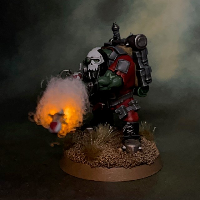

This is my tutorial for adding LED rocket launchers to miniatures. The photos show this technique applied to an Ork Kommando Rokkit Boy, but it can equally be applied to any other model with a similar rocket weapon.
I strongly recommend reading through the entire tutorial before starting work, just to make sure you have the necessary skills and tools required and that you’re not going to run into an unexpected barrier halfway through. If you need to know where to buy tools and consumables for this type of project, I have recommendations here. As well as general hobby tools supplies like glue and modelling putty, you will need the following special components as a minimum:
- 1 x Multicomp Battery Holder SMT, 20mm, CH7410-2032LF
- 1 x 3V CR2032 coin cell battery
- 1 x Miniature PCB Slide Switch
- 1 x Yellow/Amber 0805 Chip LED (3V) and 100 ohm resistor from Small Scale Lights
- A small amount of Soft Toy Stuffing
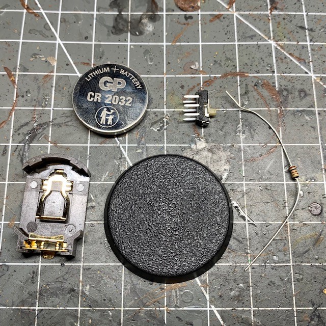
- This technique works best with a 32mm diameter circular base or larger, as this will be large enough to completely hide the battery holder. Shown below are the battery holder, CR2032 battery, slide switch and 100 ohm resistor next to the 32mm base.
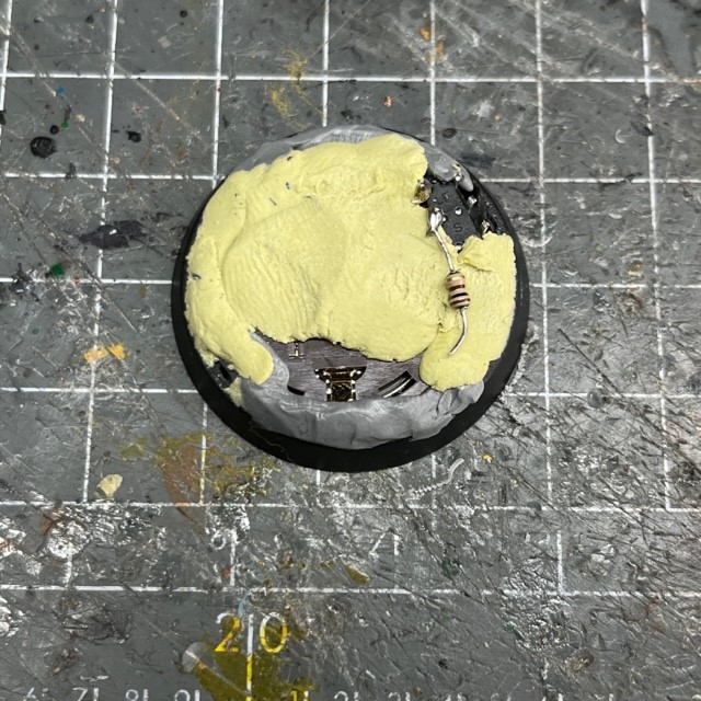
2. Cut out the top of the base, as shown below. An easy way to do this is to drill holes around the inside edge of the base and then cut between them with a craft knife. Insert the battery into the battery holder and the place the battery holder and switch into the base as shown below. The moving part of the switch should be facing down, as should the battery. This means that they will both be accessible from under the base once the model is complete.

3. It’s time to start soldering. Don’t forget that if you’re new to soldering then I have a soldering tutorial here and you can find soldering supplies here. Begin by soldering the 100 ohm resistor (this will have been supplied with your LED if you bought from Small Scale Lights) between the positive terminal and one leg of the switch, as shown below. The resistor can go anywhere in the circuit, but this is a convenient way of holding all the components together.

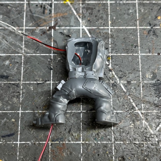
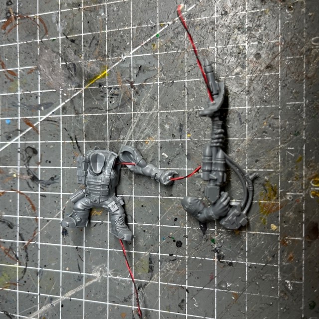
4. Next we need to start preparing the model itself. I’m using Ork Kommando 14 from the Octarius set, but these techniques can be applied to any miniature. You will need to create a path through the model for the wires to run from the LED in the gun to the battery in the base. Start by drilling through the leg. I tend to use a 1mm drill bit, but 1.5mm or 2mm would also work. It’s always best to choose the straightest leg on the model as this will be easiest to drill straight through. You will also need to drill a hole through the side of the torso where the left arm meets the shoulder. The black and red wire in the image below shows the path through the two holes that you have just drilled.
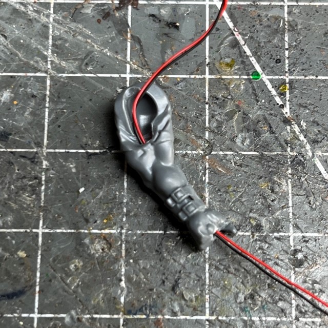
5. The next stage is to prepare the left arm. You will need to drill through from the hand to the shoulder joint. Again, a 1mm drill bit is most suitable. Again, the black and red wires in the image below show the path that you will need to drill.
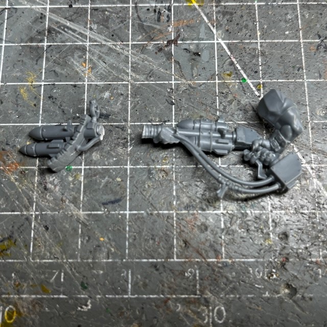
6. Now you need to prepare the rocket launcher. First, cut off the front section of the launcher as shown below. It is best to make the cut on a join between two sections in the sculpt. That way, when you reattach the two sections later, the join will be less noticeable.
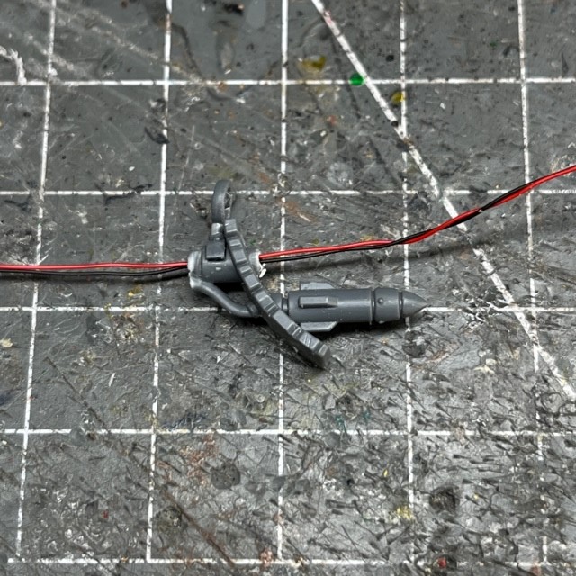
7. Now you need to drill through the shaft of the launcher and down to the wrist. This is to allow the wires of the LED to pass through the launcher and into the arm of the model, and then ultimately into the torso and the base. The eventual path of the LED wires are shown in the image below.

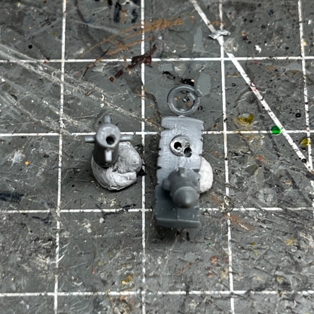
8. Cut the rocket that will be “launching” from the front of the launcher (don’t forget to put it somewhere safe), and then drill another hole through for the wire. It is best if this hole is slightly off-centre (see step 9).
9. As well as the off-centre hole to pass the wire through the front of the launcher, you will also need a more central hole in which you can mount a stiff length of 1mm metal wire. This wire will support the rocket and LED wire, and will eventually be hidden by the smoke cloud. If you do not have 1mm metal wire, an “unfolded” paperclip should also work. Drill a matching hole in the back of the rocket to mount the other end of the 1mm metal wire.
10. If you are using the Yellow/Amber 0805 Chip LED (3V) from Small Scale Lights then this will be supplied pre-wired. Feed the wire through all the holes you have made, starting with the front of the rocket launcher, as shown below.
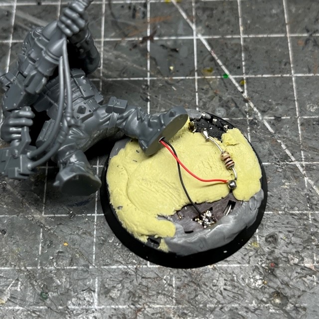
11. Fill in the gaps around the components in your base by applying modelling putty, such as Milliput of Green Stuff, to the base to hide the battery, resistor and spare wire. Make sure you leave the negative terminal and the switch terminals uncovered for now! Try not to get too much putty around the edge of the battery itself as this may make it harder to remove later when you need to change it.
12. Assemble the rest of the model components. Once assembled, pull any slack wire out through the foot, leaving about 2cm protruding from the front of the rocket launcher. When the putty on the base has set hard, the next stage is to solder the wires onto the battery holder. Connect the negative (black) wire to the negative terminal (seen on the bottom of the image below). Solder the positive (red) wire to the unused terminal of the switch. This is a good time to test the circuit. If you have done everything correctly then the LED should light up when you operate the switch. If it doesn’t then double-check your soldering connections and the polarity of the battery.
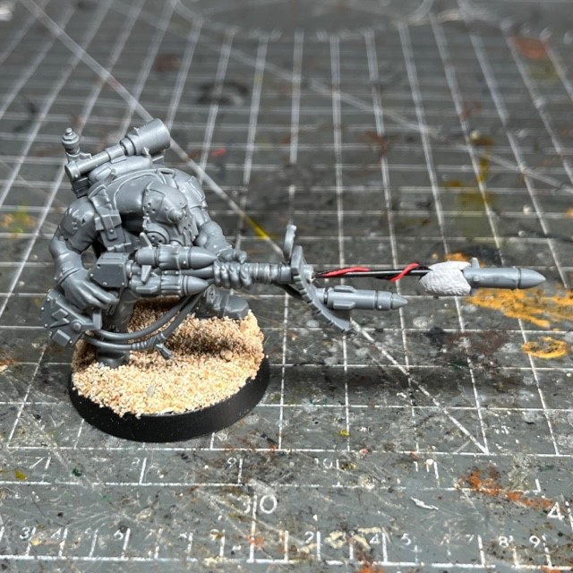
13. Cut a length of you 1mm stiff wire (or paperclip) and glue it into the holes in the front of the rocket launcher and rear of the rocket. I went with a length of 2cm for this wire, but this can be varied to personal taste. Once the wire is in place and the glue has dried, wrap the LED wire around the 1mm metal wire as shown below. Finally, glue the LED to the rear of the rocket so it is pointing backwards towards the rest of the model. Make sure you use only the bare minimum about of glue for this, as you don’t want to accidently “fog” the LED with the glue.

14. Glue the model to the base, and hide any remaining wire and battery components with more modelling putty.

15. Now you need to add texture to the base and prepare for miniature for the undercoating process. IMPORTANT: You must cover the LED during the undercoating process. This is extremely important, otherwise you could ruin all your hard work so far! I recommend using a small scrap of foil wrapped around the chip, or a blob of blu-tac, as shown below.
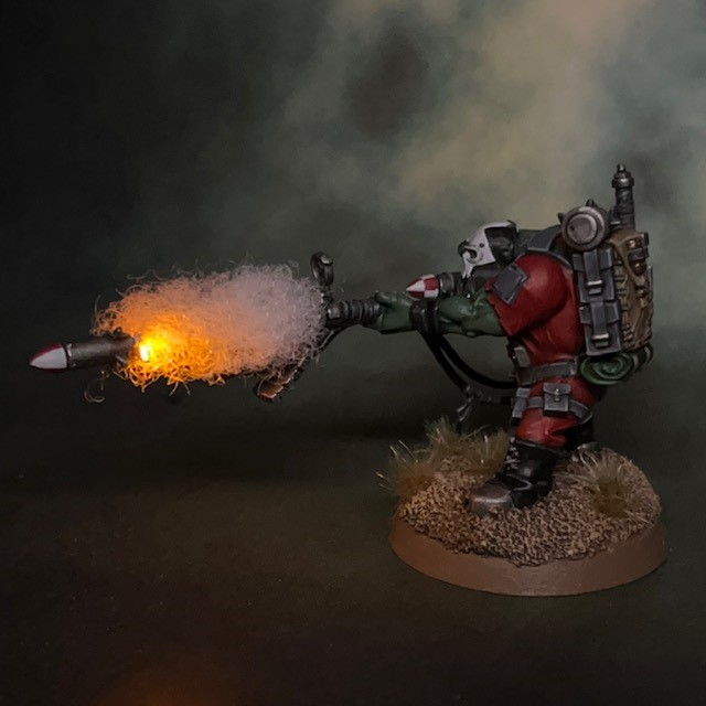
16. After undercoating, paint the model. As part of this process, I painted the LED wires and metal wire with Citadel Corax White. This is an off-white with good coverage, and will help to make the wires less visible in the “smoke trail” of the rocket.
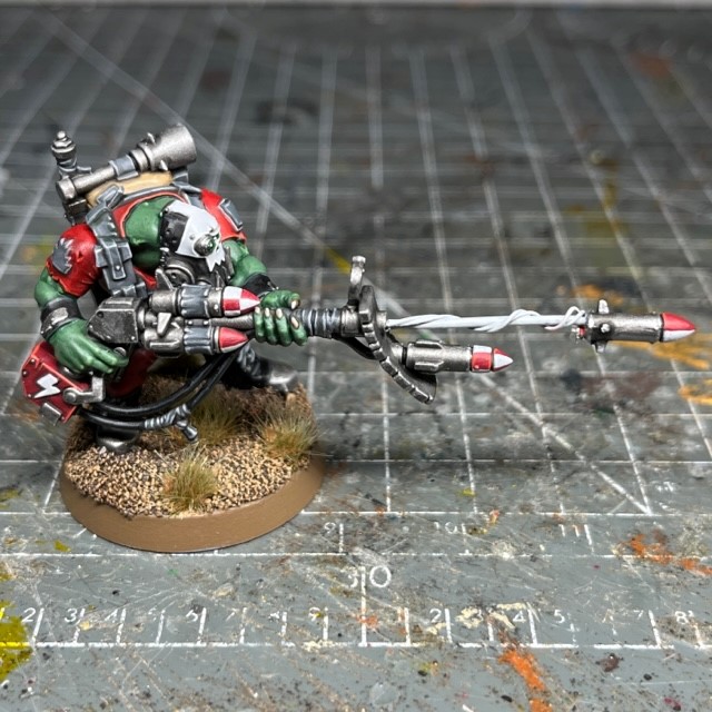
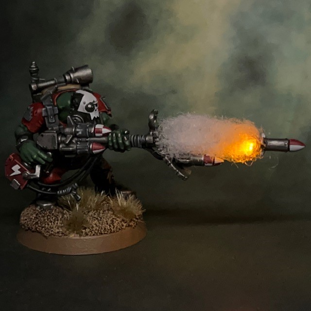
17. Apply a generous coat of PVA glue to the wires and then apply a small amount of ‘soft toy stuffing’. This is readily available from many internet craft suppliers and also Amazon. You’ll only need a small bag – this stuff goes a long way! You could also use cotton wool, but I found this stuffing has a more pleasing consistency. Wrap it around the PVA-coated wires until you get a shape you are happy with. Any excess material can be trimmed off with scissors. Once you are happy with the shape, leave the PVA to dry.

18. That’s it, you now have a finished model! If you’ve followed the tutorial correctly you should now be able to access the switch underneath the base to turn the model on and off whenever you want, and to change the battery when required.
Enjoyed this tutorial? Buy me a coffee!

All my tutorials are entirely free; the only payment I really need is seeing everyone’s awesome LED miniatures on the battlefield! Having said that, if you found these tutorials useful and you’d like to buy me a coffee to say thank you (or help keep my supplied with LEDs and website fees so I can post even more tutorials) then please click the button above. Thanks very much in advance!
